English
 русский
 Español
Content
- 1 What Aluminum Metal Casting Actually Delivers
- 2 Core Aluminum Casting Processes and When to Use Each
- 3 Selecting the Right Aluminum Alloy for Casting
- 4 Understanding and Controlling Casting Defects
- 5 Mold Design Principles That Determine Part Quality
- 6 Heat Treatment of Aluminum Castings: When and How
- 7 Machining Aluminum Castings: Speeds, Feeds, and Tool Selection
- 8 Surface Finishing Options for Aluminum Cast Parts
- 9 Quality Inspection Methods for Aluminum Casting
- 10 Cost Drivers in Aluminum Metal Casting Projects
- 11 Emerging Developments in Aluminum Casting Technology
What Aluminum Metal Casting Actually Delivers
Aluminum casting is the dominant choice for lightweight structural components across automotive, aerospace, consumer electronics, and industrial equipment—and for good reason. Aluminum alloys offer a density of roughly 2.7 g/cm³, about one-third that of steel, while high-performance casting alloys such as A380 and A356 achieve tensile strengths between 160 MPa and 330 MPa depending on heat treatment. When you combine that strength-to-weight ratio with excellent corrosion resistance, high thermal conductivity (around 96–160 W/m·K), and the ability to fill intricate mold geometries, aluminum metal casting becomes the most cost-effective path from raw metal to finished part in most mid-to-high volume production scenarios.
The direct conclusion for anyone evaluating manufacturing options: if your part weighs more than it needs to, operates in a corrosive or thermally demanding environment, and must be produced at volumes above roughly 500 units per year, aluminum casting almost certainly outperforms steel fabrication, plastic injection molding, and zinc die casting on a total-cost-per-part basis. The rest of this article explains exactly why, with specific data on processes, alloys, tolerances, and defect control.
Core Aluminum Casting Processes and When to Use Each
Not all aluminum casting methods are interchangeable. Each process has a distinct cost profile, tooling lead time, dimensional capability, and surface finish range. Choosing the wrong process can add 30–60% to per-part cost or push dimensional tolerances outside acceptable limits.
High-Pressure Die Casting (HPDC)
HPDC forces molten aluminum into a hardened steel die at pressures between 10 MPa and 175 MPa. Cycle times run as fast as 30–90 seconds per shot, making it the preferred process for volumes above 10,000 parts. Dimensional tolerances of ±0.1 mm on small features are routinely achievable. Wall thicknesses as low as 1.0–1.5 mm are possible. The main limitation is porosity: trapped gas during rapid fill creates microscopic voids that compromise pressure-tightness and reduce fatigue life. Vacuum-assisted HPDC addresses this substantially, bringing porosity levels below 0.5% by volume in well-controlled operations. Tooling cost ranges from $15,000 for a simple single-cavity die to over $100,000 for complex multi-cavity tooling, which means HPDC only makes economic sense at higher volumes.
Low-Pressure Die Casting (LPDC)
LPDC pushes molten metal upward into the die using air pressure of 0.02–0.1 MPa, resulting in a slower, more controlled fill. The controlled solidification produces denser, lower-porosity castings compared to HPDC. Automotive wheel manufacturers rely heavily on LPDC for this reason—aluminum wheels made by LPDC can achieve fatigue life improvements of 15–25% over equivalent HPDC wheels. Cycle times are longer, typically 3–8 minutes, and tooling costs are comparable to HPDC, so LPDC suits mid-volume production of structurally critical parts rather than high-volume commodity components.
Gravity (Permanent Mold) Casting
Gravity casting uses reusable steel molds without applied pressure. Metal flows in by gravity alone, producing castings with good surface finish (Ra 3.2–6.3 µm typically), low porosity, and mechanical properties well suited to heat treatment. A356-T6 parts produced by gravity casting regularly achieve yield strengths of 200–220 MPa with elongation of 6–10%, making them appropriate for safety-critical applications such as engine brackets, suspension components, and hydraulic manifolds. Tooling cost is moderate, typically $5,000–$40,000, and economic volume thresholds start around 1,000 parts per year.
Sand Casting
Sand casting remains the most flexible aluminum metal casting process. Pattern tooling costs as little as $500–$5,000, lead times from order to first casting are often under two weeks, and there is virtually no size limit—sand-cast aluminum parts range from 50-gram brackets to multi-ton pump housings. Dimensional tolerances are wider (±0.5–1.5 mm is typical), surface finish rougher (Ra 12.5–25 µm), and cycle times much longer than die casting, but for prototypes, low-volume parts, and large structural castings, sand casting is often the only practical option. Green sand, resin-bonded sand, and lost-foam variants each offer different trade-offs in accuracy and cost.
Investment Casting
Investment casting (lost-wax casting) of aluminum achieves the finest surface finish and tightest tolerances of any casting process—Ra 1.6–3.2 µm and tolerances of ±0.1–0.25 mm are standard. Complex internal geometry, undercuts, and thin walls down to 1.5 mm are achievable without cores. The process is expensive per part relative to HPDC at high volumes, but for aerospace fittings, impellers, and medical device housings where machining costs would otherwise be prohibitive, investment casting reduces total manufacturing cost considerably.
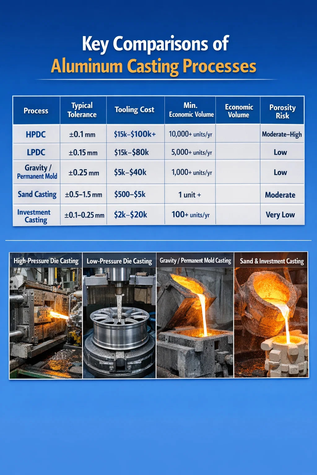
| Process | Typical Tolerance | Tooling Cost | Min. Economic Volume | Porosity Risk |
|---|---|---|---|---|
| HPDC | ±0.1 mm | $15,000–$100,000+ | 10,000+ units/yr | Moderate–High |
| LPDC | ±0.15 mm | $15,000–$80,000 | 5,000+ units/yr | Low |
| Gravity / Permanent Mold | ±0.25 mm | $5,000–$40,000 | 1,000+ units/yr | Low |
| Sand Casting | ±0.5–1.5 mm | $500–$5,000 | 1 unit+ | Moderate |
| Investment Casting | ±0.1–0.25 mm | $2,000–$20,000 | 100+ units/yr | Very Low |
Selecting the Right Aluminum Alloy for Casting
Alloy selection is arguably the single most consequential decision in aluminum casting design. The wrong alloy can produce brittleness, poor fluidity during pour, excessive shrinkage porosity, or inadequate corrosion resistance—none of which can be fixed by process optimization alone. The aluminum casting alloy family is dominated by silicon (Si) as the primary alloying element because silicon dramatically improves fluidity and reduces solidification shrinkage.
A380: The HPDC Workhorse
A380 (Al-Si8.5-Cu3.5) is the most widely used die casting alloy in the world, accounting for an estimated 50–60% of all aluminum HPDC production in North America. Its high silicon content (7.5–9.5%) gives exceptional fluidity, allowing thin walls and complex geometry. Copper additions (3–4%) boost as-cast tensile strength to approximately 324 MPa and hardness to around 80 HB. The trade-off is reduced ductility (elongation under 3%) and limited weldability. A380 is not suitable for applications requiring T5 or T6 heat treatment because copper content makes it prone to stress cracking during quench.
A356 and A357: Heat-Treatable Structural Alloys
A356 (Al-Si7-Mg0.3) and the higher-magnesium A357 (Al-Si7-Mg0.6) are the primary alloys for gravity and LPDC applications where structural performance matters. In the T6 temper (solution heat treatment at 540°C for 8–12 hours, quench, age at 155°C for 3–5 hours), A356-T6 delivers yield strength of 207 MPa, ultimate tensile strength of 262 MPa, and elongation of 6–10%. A357-T6 pushes yield strength to approximately 290 MPa. Both alloys respond well to welding and brazing, which makes them suitable for assemblies. The foundry must control magnesium content precisely—losses of 0.05% Mg during melting noticeably reduce mechanical properties.
319 Alloy: The Versatile Intermediate Option
319 (Al-Si6-Cu3.5) is widely used for engine blocks, cylinder heads, and intake manifolds where moderate strength combined with good machinability is needed. It accepts T5 and T6 treatment. As-cast tensile strength is around 185 MPa; T6 treatment raises it to approximately 250 MPa. The alloy's copper content gives slightly better elevated-temperature stability than A356, which is relevant for engine components that cycle between ambient and 200–250°C operating temperatures.
535 and 512: Marine and Corrosion-Critical Applications
When corrosion resistance is the primary design driver—marine hardware, food processing equipment, chemical handling components—magnesium-dominant alloys like 535 (Al-Mg6.2) and 512 (Al-Mg4-Si1.8) outperform silicon-dominant alloys. They show excellent resistance to seawater and salt spray without surface treatments, and have good ductility (elongation 8–13%). The penalty is poor fluidity relative to silicon alloys, which limits wall thinness and geometric complexity. Foundries casting 535 must use careful furnace practices to prevent magnesium oxidation.
| Alloy | UTS (MPa) | Yield (MPa) | Elongation (%) | Best Process Fit |
|---|---|---|---|---|
| A380 | 324 | 160 | 2–3 | HPDC |
| A356-T6 | 262 | 207 | 6–10 | Gravity, LPDC, Sand |
| A357-T6 | 325 | 290 | 4–6 | Gravity, LPDC |
| 319-T6 | 250 | 165 | 2–4 | Sand, Gravity |
| 535 | 240 | 140 | 8–13 | Sand |
Understanding and Controlling Casting Defects
Defects in aluminum castings are the primary cause of scrapped parts, warranty returns, and field failures. Understanding the root cause of each defect type is far more useful than generic quality checklists, because each defect has a different fix and often multiple plausible causes that need to be isolated systematically.
Porosity: Gas and Shrinkage
Porosity is the most common defect in aluminum metal casting and comes in two distinct types that require different interventions. Gas porosity originates from hydrogen dissolved in molten aluminum. Liquid aluminum can dissolve up to 0.69 mL/100g of hydrogen at its melting point; solid aluminum holds only about 0.036 mL/100g. During solidification, this dissolved hydrogen precipitates as spherical pores. The fix is degassing—rotary impeller degassing with nitrogen or argon for 8–15 minutes reduces hydrogen content to below 0.10 mL/100g, which is the industry standard for structural parts. Reduced-pressure test (RPT) or density measurement with Archimedes method confirms melt quality before pour.
Shrinkage porosity forms when solidifying metal contracts (aluminum shrinks approximately 3.5–8.5% by volume during solidification) and liquid metal cannot flow in to compensate. It appears as irregular, branching voids in thick sections or at hot spots. The solution is gating and risering redesign: adequate riser volume, correct riser placement above the heaviest section, and chilling of isolated thick areas to promote directional solidification toward the riser. Simulation software such as MAGMASOFT or ProCAST can predict shrinkage porosity before tooling is cut, saving significant tooling rework cost.
Cold Shuts and Misruns
A cold shut occurs when two streams of molten metal meet but fail to fully fuse, leaving a visible seam or weak plane. Misruns occur when metal solidifies before filling the mold completely. Both defects arise from insufficient metal temperature, inadequate mold temperature, or too-slow fill velocity. For HPDC, shot velocity in the second phase (die fill) typically must reach 30–60 m/s to prevent cold shuts in thin sections. Mold temperature for aluminum die casting is maintained at 150–250°C; letting it drop below 150°C reliably produces cold shut defects in walls thinner than 2 mm.
Oxide Inclusions
Aluminum forms a solid oxide skin almost instantly when exposed to air. Turbulent pouring folds this oxide film into the casting as bifilm inclusions—thin, double-layered oxide sheets that dramatically reduce fatigue life and elongation. John Campbell's bifilm theory has transformed foundry practice: the key is to fill the mold without any turbulence that folds the surface. Bottom-filling gating systems, reduced sprue height, ceramic foam filters, and slow controlled pour rates all reduce bifilm content. Fatigue life improvements of 2–5× have been documented in parts where bifilm content was reduced through gating redesign alone.
Hot Tearing
Hot tearing (hot cracking) occurs in the semi-solid state when the casting is constrained from contracting and tensile stresses exceed the strength of the partially solidified metal. It typically appears at abrupt section changes, sharp internal corners, and areas where the mold prevents free contraction. Design fixes include increasing fillet radii to a minimum of 3 mm, avoiding section thickness ratios greater than 3:1 at junctions, and designing molds with appropriate collapsibility or metal die sections that move with the casting during ejection.
Mold Design Principles That Determine Part Quality
The mold or die is where aluminum casting quality is largely determined—not on the shop floor during production, but during the design and simulation phase before any metal is cut. Experienced foundry engineers follow a set of established principles that prevent the majority of defect categories before the first trial pour.
- Parting line placement: The parting line should be at the widest cross-section of the part to minimize die complexity and allow uniform draft angles. Moving it away from cosmetic surfaces avoids flash in visible areas.
- Draft angles: External surfaces require a minimum draft of 1–2°; internal surfaces (cores) require 2–3° or more. Removing insufficient draft is one of the most common causes of die damage and casting distortion during ejection.
- Gating system design: Gates should be placed at the thickest cross-section and positioned to fill the mold progressively from bottom to top. Multiple thin gates are generally preferred over one large gate because they reduce localized heat concentration and improve fill uniformity.
- Overflow wells and venting: In HPDC, overflow wells at the end of fill paths collect cold metal, oxides, and trapped air that would otherwise become inclusions. Vents of 0.05–0.15 mm depth at the parting line allow air to escape without flashing.
- Cooling channel layout: Uniform die cooling prevents localized hot spots that cause shrinkage porosity and die soldering. Conformal cooling channels—now machinable with EDM and additive-manufactured die inserts—can reduce cycle time by 15–30% compared to conventional drilled channels.
- Ejector pin placement: Ejector pins must be distributed to apply force uniformly over the part. Pins concentrated at one end produce distortion, especially in thin-walled castings. Pin marks must be located in non-cosmetic, non-functional areas.
Heat Treatment of Aluminum Castings: When and How
Heat treatment can increase the mechanical properties of aluminum castings substantially—but only when the alloy is heat-treatable and the casting has low enough porosity that quenching will not cause blister formation. HPDC castings with standard levels of gas porosity cannot be conventionally T6 treated because the trapped gas expands during the solution heat treatment soak at 500–540°C, forming surface blisters. This is one reason HPDC is generally used in as-cast or T5 (artificial aging only, without solution treatment) condition.
T6 Treatment for Gravity and Sand Castings
For A356 and A357 gravity castings, the T6 cycle begins with solution heat treatment at 535–545°C for 8–12 hours, during which silicon particles spheroidize and Mg₂Si dissolves into the matrix. The casting is then quenched in hot water (60–80°C) rather than cold water to reduce residual stress while still achieving supersaturation. Artificial aging follows at 150–160°C for 3–5 hours. Each step is critical: under-soaking during solution treatment leaves Mg₂Si undissolved and reduces achievable strength by 10–15%; over-aging reduces strength and hardness as precipitates coarsen.
T5 Treatment for Die Castings
T5 treatment—artificial aging without prior solution treatment—is applicable to HPDC castings made with alloys that retain some supersaturation from rapid die cooling. For A380 and similar alloys, T5 aging at 155–165°C for 4–6 hours increases hardness by 10–20% and improves dimensional stability. It does not produce the property improvements of T6 but avoids porosity-related blister problems. For applications requiring full T6 properties in die cast form, vacuum die casting or squeeze casting (which produce low-porosity castings compatible with solution treatment) are the alternative routes.
Dimensional Stability and Stress Relief
Castings intended for precision machining that are not otherwise heat treated should receive a stress-relief anneal at 230–260°C for 2–4 hours. Residual stresses from solidification and ejection can cause dimensional shifts of 0.1–0.5 mm during or after machining of thin-walled features. This is particularly relevant for housing and valve body castings with closely toleranced bore locations.
Machining Aluminum Castings: Speeds, Feeds, and Tool Selection
Aluminum is among the most machinable of all casting materials, but the presence of silicon and other hard particles in casting alloys means that tool selection and cutting parameters differ from those used for wrought aluminum. Getting this right reduces tool life by a factor of 3–10× compared to suboptimal choices.
High-silicon alloys (A380, A390 with 16–18% Si) are significantly more abrasive than low-silicon alloys. Polycrystalline diamond (PCD) tooling is the standard choice for high-volume machining of these alloys, with tool life of 50,000–200,000 parts per edge compared to carbide's 2,000–10,000 parts per edge in equivalent applications. For lower-volume or less abrasive alloys (A356, 319), uncoated or TiN-coated carbide is cost-effective.
- Cutting speed: 300–1,500 m/min for carbide; 1,000–4,000 m/min for PCD on hypoeutectic alloys.
- Feed rate: 0.1–0.4 mm/tooth for milling; 0.1–0.5 mm/rev for turning.
- Tool geometry: High rake angles (12–20°) reduce cutting forces and prevent built-up edge. Polished flutes reduce aluminum adhesion.
- Coolant: Flood coolant or minimum quantity lubrication (MQL) prevents thermal expansion errors in precision bores; dry machining is possible for roughing but not finishing of tight tolerances.
Drilling and tapping of cast aluminum requires attention to peck cycles that clear chips in deep holes—aluminum's tendency to gall in tapped threads under dry conditions is a common cause of tool breakage and scrapped parts. Thread-forming taps (rather than cutting taps) produce stronger threads with no chips and are the industry standard for blind tapped holes in aluminum casting.
Surface Finishing Options for Aluminum Cast Parts
As-cast aluminum surfaces are often adequate for non-cosmetic internal components, but many applications require improved corrosion protection, hardness, or appearance. The range of surface finishing options for aluminum castings is broader than for most other cast metals.
Anodizing
Type II (standard) anodizing produces a 5–25 µm aluminum oxide layer that improves corrosion resistance and can be dyed in a wide color range. Type III (hard anodizing) produces layers of 25–75 µm with surface hardness up to 400–600 HV, suitable for wear surfaces. The limitation for cast aluminum is that high silicon content in HPDC alloys (A380 at ~9% Si) produces darker, less uniform anodized surfaces than low-silicon alloys. A356 and 6061 wrought alloy anodize to brighter, more uniform finishes. If cosmetic anodizing quality is a requirement, alloy selection must account for this from the beginning of the design process.
Chromate Conversion Coating (Alodine / Iridite)
Chromate conversion coating (MIL-DTL-5541 Class 1A or Class 3) is widely used in aerospace and defense for corrosion protection and paint adhesion. It adds virtually no dimensional build-up (0.25–1 µm) and retains electrical conductivity, which makes it suitable for EMI/RFI shielding applications. Trivalent chromate (Cr³⁺) formulations are now standard in most facilities due to hexavalent chromate (Cr⁶⁺) environmental regulations.
Powder Coating and Liquid Paint
Powder coating aluminum castings produces a durable, impact-resistant finish 60–120 µm thick. Pre-treatment (iron phosphate, zirconate, or zinc phosphate) determines coating adhesion and corrosion resistance—chrome-free zirconate pre-treatments have become standard for automotive exterior aluminum components. Liquid primer + topcoat systems are used where tighter film thickness control is required or where masking complex geometry makes powder coating impractical.
Shot Blasting and Tumbling
Shot blasting with steel or ceramic shot at 0.2–0.8 mm diameter is routinely used to clean as-cast surfaces of oxide skin, improve visual appearance, and introduce beneficial compressive residual stresses of 50–150 MPa at the surface. Controlled shot peening of A357 aerospace castings has been shown to extend fatigue life by 30–60% in high-cycle applications by this compressive stress mechanism. Tumbling (vibratory finishing) in ceramic media deburrs edges and improves surface finish uniformly on complex geometry without manual handling.
Quality Inspection Methods for Aluminum Casting
Effective quality inspection for aluminum castings requires multiple complementary methods because no single technique detects all defect types. Visual inspection, dimensional measurement, and non-destructive testing (NDT) are all necessary in a complete quality system for critical parts.
- X-ray and CT scanning: Industrial X-ray (2D radiography) is the standard method for detecting internal porosity, inclusions, and shrinkage in aluminum castings. 3D computed tomography (CT) scanning provides volumetric defect maps with voxel resolution down to 5–50 µm, enabling quantitative porosity analysis against acceptance criteria such as ASTM E2868 or ASTM E505. CT scanning is increasingly used in development and first-article inspection even when production inspection uses 2D X-ray.
- Dye penetrant inspection (DPI): DPI reveals surface-breaking defects—cracks, cold shuts, surface porosity. It is inexpensive and applicable to all aluminum alloys. Type I (fluorescent) penetrant systems using UV light detect finer defects than visible dye systems and are standard for aerospace castings per ASTM E1417.
- Coordinate measuring machine (CMM): CMM with touch probe or optical scanner verifies dimensional compliance to GD&T callouts. First-article inspection of a new casting typically requires 100% of critical dimensions to be measured on 3–5 samples; production inspection uses statistical sampling per ANSI/ASQ Z1.4 or Z1.9.
- Hardness testing: Brinell hardness (HBW 5/250) is standard for aluminum castings. It provides a quick, indirect verification that heat treatment was correctly performed—A356-T6 should show 75–90 HB; as-cast A380 shows 75–85 HB. Hardness testing does not replace tensile testing for specification compliance but is useful for 100% production screening.
- Tensile and fatigue testing: Destructive mechanical testing is performed on separately cast test bars or on cut-up production castings at frequencies specified by customer standards or internal quality plans. ASTM B108 governs test bar casting procedures for gravity and permanent mold castings.
Cost Drivers in Aluminum Metal Casting Projects
Understanding where cost accumulates in an aluminum casting project allows buyers and engineers to make design and sourcing decisions that reduce total cost rather than just optimizing individual line items. The five largest cost drivers in most aluminum casting programs are tooling amortization, raw material, energy, scrap rate, and secondary operations.
Tooling Amortization
At low volumes, tooling cost dominates per-part cost. A $50,000 HPDC die amortized over 10,000 parts adds $5.00 per part in tooling cost alone. At 100,000 parts, it contributes $0.50 per part. This is why process selection at low volumes should favor sand casting or low-cost gravity tooling even if per-cycle cost is higher—the tooling amortization arithmetic usually wins at volumes below 2,000–5,000 parts per year.
Alloy Cost and Metal Yield
Primary aluminum ingot cost fluctuates with the LME price, which has ranged from $1,500 to $3,800 per metric ton over the past decade. Secondary (recycled) aluminum costs 20–40% less than primary and is used in the majority of die casting operations. Metal yield—the ratio of finished casting weight to total metal poured—varies from 50–60% for sand casting (with large risers) to 80–92% for HPDC (with efficient gating). A 10% improvement in yield on a 500-ton-per-year operation at $2,000/ton aluminum cost reduces material cost by $100,000 annually.
Scrap Rate and Its Downstream Impact
Scrap rate in aluminum casting operations ranges from under 2% at well-run high-volume HPDC facilities to 10–20% during new program launches or at foundries with poor process control. Every 1% increase in scrap rate adds approximately 1% to per-part cost before considering the cost of any secondary operations already performed on scrapped parts. For parts that receive significant machining before the defect is detected, the cost per scrapped unit can be 3–5× the casting cost alone. This is why investing in real-time process monitoring—cavity pressure sensors, thermal imaging of die temperature, shot profile analysis—has a positive ROI even at moderate production volumes.
Secondary Operations
Machining, heat treatment, surface finishing, assembly, and leak testing are secondary operations that frequently exceed casting cost in the total part cost equation. A casting that costs $4.00 to produce may cost $18.00 after machining, $3.00 after heat treatment, and $2.00 after surface finish—totaling $27.00 before any margin. Design for manufacturing (DFM) review focused on reducing secondary operations—eliminating unnecessary machined features, using as-cast surfaces where tolerances allow, designing-in self-locating features for fixturing—routinely reduces total manufacturing cost by 15–30% without compromising part function.
Emerging Developments in Aluminum Casting Technology
The aluminum casting industry has seen more technical advancement in the past ten years than in the preceding three decades, driven primarily by automotive electrification and lightweighting requirements. Several specific developments are reshaping what aluminum casting can produce and at what cost.
Gigacasting and Structural Die Casting
Tesla's adoption of large-format HPDC machines (6,000–9,000 ton clamping force) to produce entire rear underbody structures as single castings—replacing 70–100 individual stamped and welded steel parts—has triggered broad interest in structural die casting. The manufacturing approach reduces part count, eliminates welding and assembly labor, and reduces weight. The technical challenge is maintaining porosity levels low enough for structural integrity at these scales. Alloys developed specifically for structural die casting, including Silafont-36 and Aural-2, offer higher ductility (elongation 10–15%) than standard A380 in the as-cast condition without heat treatment, enabling T6 upgrades when needed.
Semi-Solid Metal Casting (Rheocasting and Thixocasting)
Semi-solid metal (SSM) processing injects aluminum in a partially solidified, slurry state (40–60% solid fraction) rather than fully liquid. The thixotropic slurry flows under pressure but has much lower turbulence than liquid HPDC, resulting in minimal gas entrainment and oxide bifilm content. SSM castings achieve porosity levels below 0.1% and are fully compatible with T6 heat treatment, producing mechanical properties approaching wrought aluminum. The process cost premium is 20–40% over conventional HPDC, but for applications where structural integrity and heat treatability are required in a die-cast form factor, SSM is technically unmatched.
Simulation-Driven Die Design
Casting simulation software (MAGMASOFT, ProCAST, Flow-3D Cast) has advanced to the point where fill pattern, solidification sequence, thermal gradients, and residual stress distributions can be predicted with high accuracy before tooling is manufactured. Foundries that invest in simulation capability report 30–50% reductions in tooling trials and first-article rejections. The economic case is straightforward: a simulation package costing $30,000–$80,000 per year saves substantially more in tooling rework and scrap at any foundry running more than $2–3 million in annual tooling projects.
Additive Manufacturing for Tooling and Cores
3D-printed sand molds and cores—produced by binder jet printing of silica sand—have reduced sand casting lead times from weeks to days and enabled complex internal geometries impossible with conventional core box tooling. A sand core that previously required a $15,000 core box tool and 6-week lead time can now be printed in 24–48 hours for $200–$800. For die casting, additive-manufactured conformal cooling inserts and shot sleeve liners produced by laser powder bed fusion improve thermal management and die life measurably in high-production programs.