 LANGUAGE
  English
 русский
 Español

Content
- 1 What Is a Cast Aluminum Mold and Why It Matters
- 2 Types of Molds Used in Aluminum Casting
- 3 Mold Material Selection for Aluminum Casting
- 4 Aluminum Alloys Most Commonly Cast in These Molds
- 5 Critical Design Rules for Cast Aluminum Molds
- 6 The Aluminum Casting Process Step by Step
- 7 Common Defects in Aluminum Casting and Their Mold-Related Causes
- 8 Surface Treatment and Coating Options for Cast Aluminum Molds
- 9 Cost Structure of Cast Aluminum Mold Tooling
- 10 Mold Maintenance and Life Extension Practices
- 11 Emerging Technologies Changing Cast Aluminum Mold Design
What Is a Cast Aluminum Mold and Why It Matters
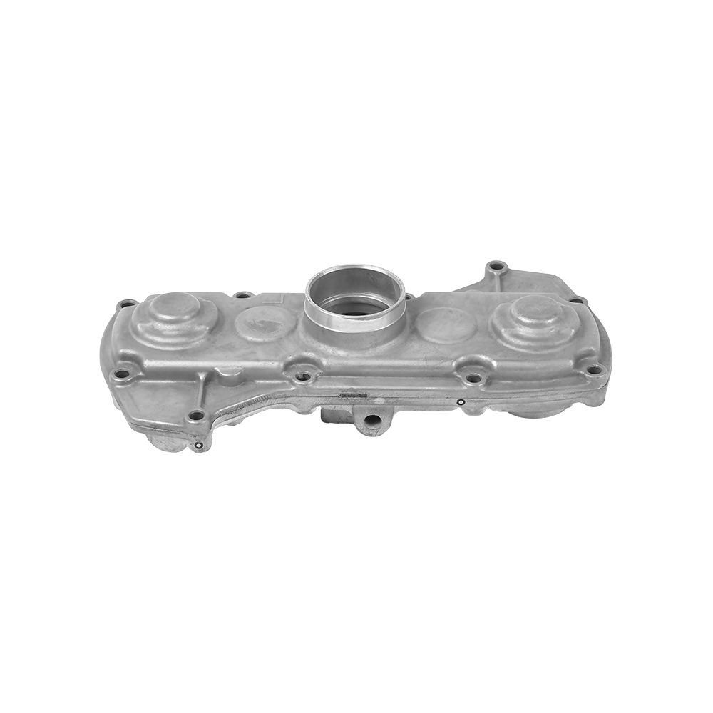
A cast aluminum mold is a precision tooling component used to shape molten aluminum into a defined geometry during the aluminum casting process. Unlike sand molds that are destroyed after each use, a properly engineered cast aluminum mold — whether made from tool steel, H13 die steel, or aluminum alloy itself — can withstand thousands to hundreds of thousands of cycles depending on the casting method employed.
The mold is not a passive container; it actively governs metallurgical outcome. Its thermal conductivity, venting design, gate location, and surface finish all directly influence the mechanical properties of the final aluminum casting. A poorly designed mold introduces porosity, cold shuts, shrinkage cavities, and dimensional inaccuracies that no downstream process can fully correct.
This article walks through mold types, material selection, process parameters, design principles, and cost benchmarks — covering everything a product engineer, tooling buyer, or foundry operator needs to make confident decisions about cast aluminum molds.
Types of Molds Used in Aluminum Casting
Not all aluminum casting processes use the same mold construction. The choice of mold type defines cycle time, surface finish, dimensional tolerance, and part complexity ceiling. Below are the five main categories used across the industry.
Sand Molds
Sand casting uses a bonded sand mixture packed around a pattern to form a single-use mold cavity. Green sand molds are the most economical option for low-volume aluminum casting, with tooling costs often under $2,000 for a simple part. Dimensional tolerance is typically ±0.030 inches per inch, and surface roughness runs 250–500 Ra. Sand molds are suitable for parts weighing from a few grams up to several hundred kilograms, making them the go-to choice for prototype runs, large structural components, and short production series.
Permanent Metal Molds (Gravity Die Casting)
A permanent cast aluminum mold made from gray iron or tool steel is reused for thousands of cycles. Gravity die casting fills the mold using only gravitational force, producing denser, stronger parts than sand casting because the faster solidification rate refines the grain structure. Mold life for aluminum parts typically reaches 50,000–100,000 shots with proper maintenance. Dimensional tolerance improves to ±0.010–0.015 inches per inch, and surface roughness drops to 125–250 Ra.
High-Pressure Die Casting Molds
High-pressure die casting (HPDC) injects molten aluminum into a hardened H13 tool steel mold at pressures between 1,500 and 25,000 psi and injection speeds of 10–100 m/s. The result is the fastest cycle time in aluminum casting — often 30–120 seconds per shot — and the tightest tolerances available without machining, typically ±0.002–0.005 inches per inch. A single HPDC mold can cost $30,000 to $200,000, but the high per-shot volume (500,000+ cycles for properly maintained tooling) drives unit cost down to fractions of a dollar for commodity parts.
Low-Pressure Die Casting Molds
Low-pressure die casting (LPDC) fills a metal mold from below using 0.7–1.0 bar of pressurized gas applied to the melt surface. The controlled, laminar fill pattern reduces oxide entrapment and porosity compared to gravity or high-pressure methods. This makes LPDC the dominant process for automotive aluminum wheels and structural nodes, where pressure-tight integrity and consistent mechanical properties are mandatory. Mold costs sit between permanent mold and HPDC tooling, typically $15,000–$80,000.
Investment Casting Shells
Investment casting (lost-wax casting) builds a ceramic shell around a wax pattern, which is then melted out before molten aluminum is poured. The mold is destroyed per cycle, but the wax-injection die that forms the pattern is permanent. This process achieves the finest surface finish in aluminum casting — as low as 63–125 Ra — and tolerances of ±0.005 inches per inch, making it appropriate for aerospace brackets, impellers, and medical implants.
Mold Material Selection for Aluminum Casting
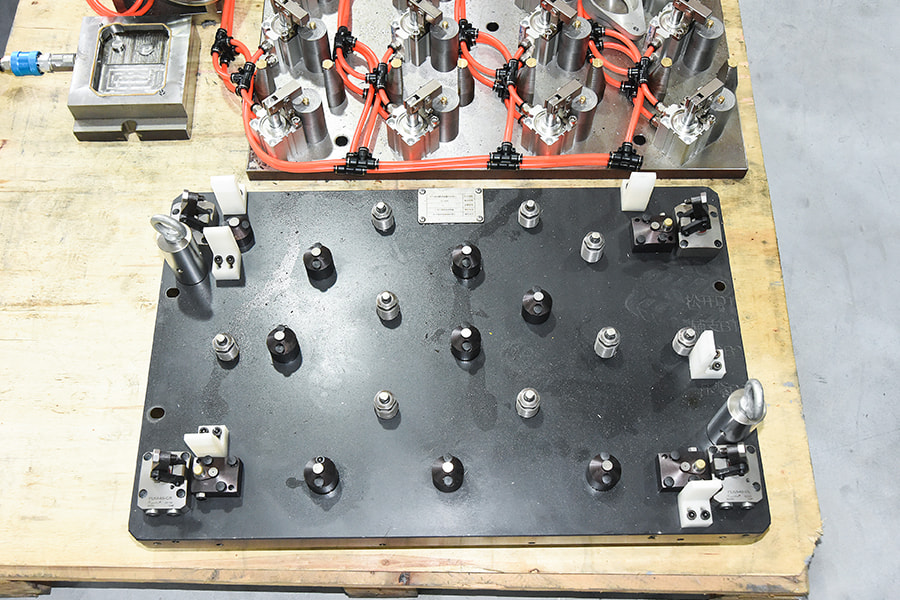
The material used to build the cast aluminum mold has a direct impact on tool life, heat management, part quality, and total cost of ownership. The following table compares the most commonly used mold materials in aluminum casting applications.
| Material | Typical Application | Approx. Tool Life (shots) | Key Advantage | Key Limitation |
|---|---|---|---|---|
| H13 Tool Steel | HPDC, LPDC | 300,000–1,000,000 | Best thermal fatigue resistance | High cost, long lead time |
| Gray Cast Iron | Gravity permanent mold | 50,000–100,000 | Low cost, good machinability | Brittle, limited pressure rating |
| P20 Steel | Prototype HPDC, gravity die | 50,000–150,000 | Pre-hardened, fast machining | Lower heat resistance than H13 |
| Aluminum Alloy (7075) | Prototype molds, short runs | 500–5,000 | Fastest machining, lowest cost | Poor thermal fatigue life |
| Beryllium-Copper | Core inserts, hot spots | 200,000–500,000 | Highest thermal conductivity | High cost, health hazards when machining |
H13 remains the industry standard for production-grade cast aluminum mold tooling in high-pressure applications. When heat treated to 44–48 HRC, it resists the repeated thermal cycling that causes heat checking — the network of surface cracks that degrades mold cavity surface finish and ultimately leads to part flash and dimensional drift. For prototype or bridge tooling, an aluminum mold made from 7075-T6 can be CNC-machined in 2–5 days at costs 60–80% lower than an equivalent H13 tool, albeit with very limited production life.
Aluminum Alloys Most Commonly Cast in These Molds
The alloy poured into the cast aluminum mold is just as important as the mold itself. Different aluminum casting alloys have different fluidity, shrinkage behavior, hot-tear tendency, and final mechanical properties. Matching alloy to process and mold design is fundamental to achieving consistent, defect-free parts.
A380 — The HPDC Workhorse
A380 (AlSi8Cu3Fe) accounts for roughly 85% of all aluminum die casting production in North America. Its composition — approximately 8.5% silicon, 3.5% copper — gives it excellent fluidity at typical die casting temperatures of 620–680°C, good resistance to hot cracking, and adequate mechanical properties: tensile strength around 324 MPa, yield strength 160 MPa, and elongation 3.5% in the as-cast condition. A380 is the default choice when no specific property requirement drives a different alloy selection, and its widespread use means it is well-understood by every HPDC mold shop.
A356 — The Structural and Heat-Treatable Option
A356 (AlSi7Mg0.3) is the dominant alloy for gravity permanent mold and low-pressure die casting where mechanical performance is the priority. Unlike A380, A356 responds to T6 heat treatment, achieving tensile strengths of 262–310 MPa and yield strengths of 186–255 MPa with elongation values of 5–10%. Automotive suspension components, steering knuckles, and aerospace structural brackets are routinely cast in A356 using precision cast aluminum molds. The trade-off is narrower process windows: A356 is more sensitive to hydrogen gas porosity and requires careful melt degassing and mold venting design.
A413 — Maximum Fluidity for Thin Walls
With approximately 12% silicon content near the eutectic composition, A413 has the highest fluidity of any common aluminum casting alloy. It fills thin sections and intricate geometries that would cause misruns in A380 or A356. Minimum wall thicknesses of 0.8 mm are achievable in well-designed HPDC molds with optimized gate and runner systems. A413 is the standard choice for decorative hardware, lighting housings, and communication equipment enclosures where cosmetic surface quality and form complexity take precedence over structural loading.
535 (Almag 35) — Corrosion-Resistant Applications
Alloy 535 contains approximately 6.2% magnesium with minimal silicon and copper, giving it outstanding corrosion resistance and excellent machinability but making it significantly more challenging to cast. Its solidification range is wide, increasing hot-tear susceptibility, and it oxidizes rapidly during melting and pouring. Cast aluminum molds used for 535 require carefully designed gating to promote directional solidification and must be preheated to 250–300°C to reduce thermal shock at the mold face.
Critical Design Rules for Cast Aluminum Molds
A mold that looks geometrically correct on a CAD screen can still produce scrap at rate if the underlying engineering principles are not respected. The following design rules apply broadly across aluminum casting processes, with process-specific adjustments noted where relevant.
Draft Angle
All surfaces parallel to the draw direction of the mold must carry draft to allow clean part ejection without drag marks or part distortion. For HPDC aluminum casting, a minimum of 1–2° internal draft and 0.5–1° external draft is the standard starting point on textured or polished surfaces respectively. Deeper cavities and coarser textures require more draft. Insufficient draft causes ejector pin witness marks, part sticking, and accelerated mold wear on cavity walls.
Wall Thickness Uniformity
Non-uniform wall thickness creates differential solidification rates that result in porosity, sink marks, and residual stress concentrations. For HPDC aluminum casting, the recommended nominal wall thickness range is 1.5–5 mm, with transitions between thick and thin sections following a taper ratio of at least 3:1 in length to thickness change. Where a thick boss or rib intersects a thin wall, the fillet at the base should have a radius equal to at least 50% of the adjacent wall thickness to reduce stress concentration factors.
Gate and Runner Design
The gating system controls fill velocity, fill pattern, and the location where turbulence and oxide films enter the casting cavity. For HPDC, gate velocity at the in-gate is typically designed for 25–50 m/s to ensure complete fill within the mold's solidification window, which for most aluminum alloys is 0.01–0.1 seconds. Fan gates distribute flow across a wide entrance to reduce jetting and entrapped air. In gravity permanent mold aluminum casting, bottom-fill or step-gating systems that introduce metal from below the melt surface are strongly preferred over top-pour arrangements, which generate oxide layers as metal falls through air.
Venting and Overflow Wells
Air and gases displaced by the incoming metal must escape through dedicated vents, or they become entrapped porosity in the part. HPDC molds use vents ground into the parting line at 0.07–0.12 mm depth (shallow enough to prevent metal penetration but deep enough to pass gas at injection velocity) with a total vent area typically equal to 25–50% of the in-gate area. Overflow wells connected at the end of flow paths capture cold metal and oxide-rich front material, keeping the bulk of the casting metallurgically clean.
Cooling Channel Layout
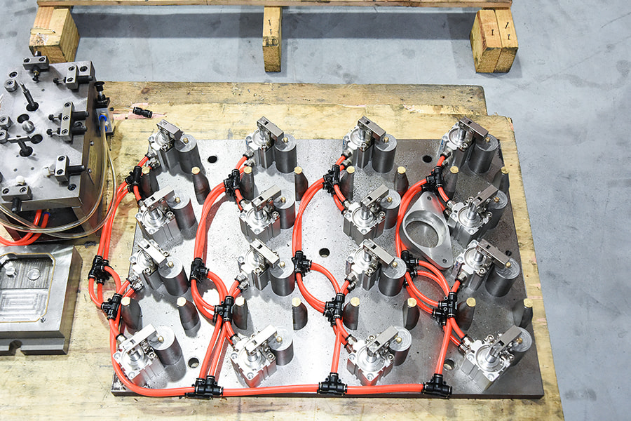
Thermal management through mold cooling channels is not an afterthought — it defines cycle time and part consistency. Cooling channels should be placed as close as practical to the cavity surface, typically 15–25 mm from the face, with a channel diameter of 8–12 mm and spacing of 2–3× channel diameter center-to-center. Conformal cooling channels produced by additive manufacturing of mold inserts can follow the part contour precisely, reducing cycle time by 15–30% compared to conventional straight-drilled channels in geometrically complex molds.
The Aluminum Casting Process Step by Step
Understanding what happens at each stage of the aluminum casting process helps troubleshoot defects and identify where mold design changes will deliver the most impact.
- Melt Preparation: Aluminum alloy ingots or returns are melted in a gas-fired or electric resistance furnace. The melt is degassed using rotary impeller units that inject argon or nitrogen to remove dissolved hydrogen (target density index below 1% for structural casting). Flux additions remove oxide inclusions. Melt temperature at the furnace is typically 720–760°C.
- Mold Preparation: The cast aluminum mold is preheated to 150–250°C (HPDC) or 250–400°C (gravity permanent mold) to prevent premature solidification of thin sections and thermal shock to the mold steel. A release agent or die lubricant is sprayed onto cavity surfaces to prevent aluminum soldering (welding) to the mold face.
- Fill: Molten aluminum is introduced into the mold cavity through the gating system. Fill time for HPDC is 10–100 milliseconds. For gravity and LPDC, fill time ranges from 5–60 seconds depending on part volume and gating design.
- Solidification: Heat is extracted through the mold walls and cooling channels. The solidification front progresses from the mold surface inward. HPDC applies intensification pressure (10,000–25,000 psi) during solidification to compress entrapped gas and compensate for shrinkage.
- Ejection: Once the part has reached sufficient rigidity (still above 200°C in many cases), the mold opens and ejector pins advance to push the casting off the cavity surface. Proper draft and lubrication minimize drag and distortion during this stage.
- Trimming and Post-Processing: Gates, runners, overflows, and flash are removed by trim dies, band saws, or CNC machining. Heat treatment (T5, T6) is applied where required. Secondary machining achieves features impractical to cast directly, such as tapped holes, precision bores, and sealing surfaces.
Common Defects in Aluminum Casting and Their Mold-Related Causes
Most aluminum casting defects can be traced back to mold design, mold condition, or process parameter settings that interact with the mold. Correctly diagnosing the root cause prevents repeated scrap and costly process trials.
Porosity
Porosity is the most frequently cited defect in aluminum casting, appearing as voids inside the part cross-section or on machined surfaces. Gas porosity results from hydrogen dissolved in the melt precipitating during solidification or from air entrapment during fill. Shrinkage porosity forms in isolated thick sections that solidify last without sufficient feed metal. Mold-related causes include inadequate venting (trapping air), poorly located overflows, cold mold temperatures that freeze the gate before the cavity is fully pressurized, and thick-thin wall transitions without proper gating to maintain feeding paths.
Cold Shuts and Misruns
Cold shuts are visible seams on the part surface where two flow fronts met but failed to fuse due to an oxide skin or insufficient superheat. Misruns occur when the melt solidifies before reaching the end of the cavity. Both defects indicate the mold is too cold, the fill velocity is too low, or the gating system is forcing metal to travel too far before joining. Adding gates closer to the problem zone, raising mold preheat temperature, or increasing injection speed are the standard corrective actions.
Soldering (Metal Sticking to the Mold)
Soldering occurs when aluminum alloy welds to the mold cavity face, particularly in zones of high velocity impact or elevated mold temperature. It produces surface tears on the casting and accelerates mold erosion. Iron content in the aluminum alloy above 0.8% acts as the primary barrier against soldering, which is why A380 (typical iron content 0.7–1.1%) was specifically formulated for HPDC. Mold surface treatments such as physical vapor deposition (PVD) coatings of CrN or TiAlN, nitriding of H13 inserts to 900–1100 HV surface hardness, and consistent application of water-based die lubricants are the engineering countermeasures.
Flash
Flash is thin fin-like extrusions of aluminum that form at the parting line or at ejector pin locations. It indicates that the clamping force is insufficient to resist the injection pressure, that the parting line has worn or been damaged, or that the vents are too deep and allowing metal penetration. In a healthy HPDC operation, flash should be rare and correctable without mold rework. Chronic flash demands dimensional inspection of the parting line surfaces and a review of the press tonnage calculation using the projected area of the casting plus runners multiplied by the intensification pressure.
Heat Checking
Heat checking refers to the network of fine surface cracks that develop on mold cavity faces after repeated thermal cycling. These cracks transfer as raised veining on casting surfaces. The thermal fatigue mechanism is driven by the temperature differential between the hot surface exposed to molten aluminum (typically 300–450°C in HPDC) and the water-cooled interior. Mold steel selection (H13 with appropriate heat treatment), controlled mold preheating before production starts, and avoiding water quenching of the cavity with cold water between shots all extend time to heat check formation.
Surface Treatment and Coating Options for Cast Aluminum Molds
Surface treatments applied to the cast aluminum mold cavity extend life, reduce soldering, improve release, and in some cases allow mold repair without full cavity replacement.
- Gas Nitriding: Diffuses nitrogen into the H13 steel surface at 500–530°C to achieve a compound layer (white layer) of 5–15 µm and a diffusion zone to 0.3 mm depth. Resulting surface hardness of 900–1100 HV greatly improves erosion and soldering resistance. Standard maintenance interval for HPDC molds is re-nitriding every 50,000–100,000 shots.
- PVD Coatings (CrN, TiAlN, DLC): Physical vapor deposition coatings of 2–5 µm thickness improve release behavior and soldering resistance without changing cavity dimensions meaningfully. Diamond-like carbon (DLC) coatings at 1–3 µm provide the lowest friction coefficient (0.05–0.15 vs. steel) and excellent wear resistance but have limited thermal stability above 300°C.
- Electroless Nickel Plating: Deposits a uniform 25–75 µm nickel-phosphorus layer that improves corrosion resistance and provides a moderately hard (500–600 HV after heat treatment) release surface. Used more commonly in gravity permanent mold aluminum casting than HPDC due to lower process temperatures.
- Laser Texturing: Laser-engraved micro-patterns on the mold face create a controlled air cushion that reduces metal-to-mold contact area, improving release and reducing soldering. This technique is increasingly adopted for mold zones that experience chronic sticking problems despite conventional lubrication.
- Weld Repair: Cavities damaged by heat checking, erosion, or impact can often be restored by TIG or laser welding using H13 filler wire, followed by re-machining and re-nitriding. The economics of repair versus new cavity fabrication depend on the extent of damage and remaining cavity life, but weld repair typically costs 20–40% of a new insert.
Cost Structure of Cast Aluminum Mold Tooling
Tooling cost is often the primary concern when planning a new aluminum casting program, particularly for development teams transitioning from prototype quantities to production volumes. The numbers below reflect typical North American and European mold shop pricing in 2024 and are intended as planning benchmarks rather than quotation substitutes.
| Process | Simple Part | Medium Complexity | High Complexity | Typical Lead Time |
|---|---|---|---|---|
| Sand Casting Pattern | $500–$2,000 | $2,000–$8,000 | $8,000–$30,000 | 1–4 weeks |
| Gravity Permanent Mold | $5,000–$15,000 | $15,000–$40,000 | $40,000–$100,000 | 6–14 weeks |
| Low-Pressure Die Casting | $15,000–$30,000 | $30,000–$80,000 | $80,000–$200,000 | 10–18 weeks |
| High-Pressure Die Casting | $30,000–$60,000 | $60,000–$150,000 | $150,000–$500,000+ | 12–24 weeks |
| Investment Casting Die | $3,000–$8,000 | $8,000–$25,000 | $25,000–$80,000 | 4–10 weeks |
The high upfront cost of a production HPDC cast aluminum mold is justified by the per-shot economics at volume. A part with a tooling cost of $100,000 spread over 500,000 shots contributes only $0.20 per part to the amortized tool cost. At 50,000 shots, the same tooling cost contributes $2.00 per part — potentially making gravity die casting or investment casting more cost-effective for that production quantity despite their higher per-shot cycle times.
The break-even volume between sand casting and permanent mold aluminum casting typically falls between 2,000 and 10,000 parts, depending on part geometry, weight, and required surface finish. Below that threshold, the tooling investment in a metal mold rarely pays back on unit cost savings alone before the program ends or the design changes.
Mold Maintenance and Life Extension Practices
A cast aluminum mold is a capital asset that can deliver significantly more than its nominal tool life if maintained correctly. Foundries that implement structured preventive maintenance programs consistently achieve 20–40% longer mold life compared to reactive-only maintenance approaches.
Scheduled Inspection Intervals
Molds should be pulled from production for inspection at defined shot intervals — typically every 25,000–50,000 shots for HPDC tooling. Inspection includes dimensional checks of critical cavity features, parting line condition assessment, vent and overflow depth measurement, cooling channel flush-through test, and visual examination of cavity faces for early-stage heat checking or erosion. Catching a heat check at 0.1 mm depth allows polishing and re-nitriding to fully restore the surface; waiting until the same crack reaches 0.5 mm means weld repair and possible dimensional rework.
Lubrication Management
Die lubricant application in HPDC is a significant variable in mold life and part quality. Excessive lubricant application causes lubricant burn-on deposits on the cavity face, which generate porosity and surface blemishes. Insufficient lubricant increases soldering risk and ejection force. Automated spray systems with pressure and flow monitoring, combined with regular cleaning of nozzle orifices, maintain consistent coverage. Water-based lubricants at dilution ratios of 1:80 to 1:150 are standard for aluminum die casting, with higher dilution used in hotter cavity zones.
Mold Preheat Protocol
Starting production on a cold mold is one of the fastest ways to initiate heat checking. Thermal shock from the first shots into a mold at room temperature creates steep temperature gradients that exceed the tensile strength of the surface layer. HPDC molds should be preheated to a minimum of 150°C — and ideally 200°C — before the first production shot, using gas flame torches, infrared panel heaters, or circulating hot oil through the cooling channels. The warm-up shot sequence should run 10–20 slow-injection shots before transitioning to full production parameters.
Documentation and Shot Counter Tracking
Every maintenance action, repair, inspection finding, and process deviation should be recorded against the mold's shot count in a dedicated tooling log. This data enables predictive maintenance scheduling, supports warranty claims with mold shops, and provides the empirical basis for mold life projections on future programs using similar geometry and alloy combinations. Foundries that lack this documentation routinely discover mid-production that their mold has exceeded its design life without any warning, resulting in emergency tooling expenditure and production downtime.
Emerging Technologies Changing Cast Aluminum Mold Design
The cast aluminum mold industry is not static. Several technologies adopted over the last decade are changing what is achievable in mold design, cooling efficiency, and lead time.
Additive Manufacturing for Conformal Cooling Inserts
Laser powder bed fusion (LPBF) 3D printing in H13 and maraging steel enables cooling channels that follow the three-dimensional contour of the cavity surface — something impossible with conventional CNC drilling. Conformal cooling inserts installed in HPDC molds have demonstrated cycle time reductions of 15–35% and surface temperature uniformity improvements that reduce thermal fatigue-related heat checking. The cost premium for additive inserts over conventional inserts runs 30–80%, but this is frequently recovered within 50,000–100,000 cycles through productivity gains and reduced scrap rates.
Simulation-Driven Mold Design
Casting simulation software (MAGMASOFT, ProCAST, Flow-3D Cast) allows engineers to evaluate fill patterns, solidification behavior, shrinkage porosity probability, and thermal stress distribution in the mold before a single chip of steel is cut. Early adopters of simulation-driven design report first-shot success rates above 80% for new aluminum casting molds, compared to 40–60% for designs developed through experience and trial and error. Simulation is now considered a standard deliverable in mold design reviews for any automotive or aerospace aluminum casting program.
Vacuum-Assisted Die Casting
Vacuum systems integrated into HPDC molds evacuate the cavity to 50–100 mbar before metal injection, eliminating the primary source of gas porosity — entrapped air. The cast aluminum mold must be designed with sealed parting lines and dedicated vacuum vents. Vacuum-cast parts can be heat treated (T5, T6) to achieve mechanical properties approaching those of gravity-cast or wrought aluminum, opening HPDC to structural applications previously reserved for slower, lower-pressure processes. Wall thicknesses below 1.5 mm with high structural integrity are achievable with vacuum assistance in well-designed tooling.
Mega-Casting and Large-Format HPDC
Tesla's Gigapress concept — casting large structural assemblies such as rear underbody sections in a single HPDC shot on 6,000–9,000-ton clamping force machines — represents the largest cast aluminum molds ever built for automotive production. These single molds replace 70–100 individual stamped and welded components, reducing part count, assembly time, and weight. The molds themselves cost $3–10 million and require facilities designed specifically around the machine's physical footprint, but the total system economics have prompted every major automotive OEM to announce similar programs between 2023 and 2027.