 LANGUAGE
  English
 русский
 Español

Content
- 1 Custom Aluminum Castings: The Direct Answer Before the Details
- 2 Aluminum Casting Processes Compared: Sand, Die, Investment, and Gravity
- 3 Choosing the Right Aluminum Alloy for Custom Castings
- 4 Design Rules That Reduce Casting Defects and Cost
- 5 Mold Design and Gating System Fundamentals
- 6 How Casting Defects Form and How They Are Prevented
- 7 Dimensional Tolerances and Quality Control for Aluminum Castings
- 8 Surface Finishing and Post-Casting Machining Options
- 9 Where Custom Aluminum Castings Are Used
- 10 Casting vs Forging vs CNC Machining vs Stamping
- 11 From Prototype to Production: A Realistic Project Timeline
- 12 How Custom Aluminum Casting Is Priced
- 13 Recycled Content and the Environmental Profile of Aluminum Casting
- 14 Packaging, Traceability, and Shipping Considerations
- 15 Working With a Custom Aluminum Casting Manufacturer
- 16 Frequently Asked Questions About Custom Aluminum Castings
- 16.1 How much does custom aluminum casting tooling cost?
- 16.2 What is the minimum order quantity for a custom aluminum casting?
- 16.3 Can aluminum castings be welded?
- 16.4 How long does it take to get a custom aluminum casting produced?
- 16.5 What causes porosity in aluminum castings and can it be prevented?
- 16.6 Is aluminum casting more cost-effective than CNC machining from billet?
- 16.7 Can a die-cast aluminum part be heat treated?
- 16.8 What is the difference between as-cast surface finish and machined surface finish?
- 16.9 How do I know which wall thickness my part needs?
- 16.10 What certifications or documentation should a casting supplier provide?
Custom Aluminum Castings: The Direct Answer Before the Details
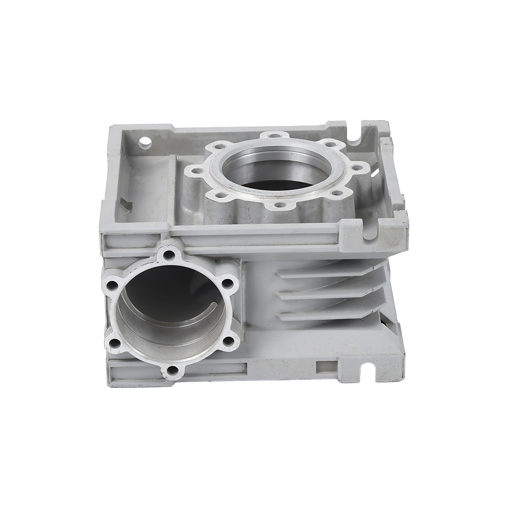
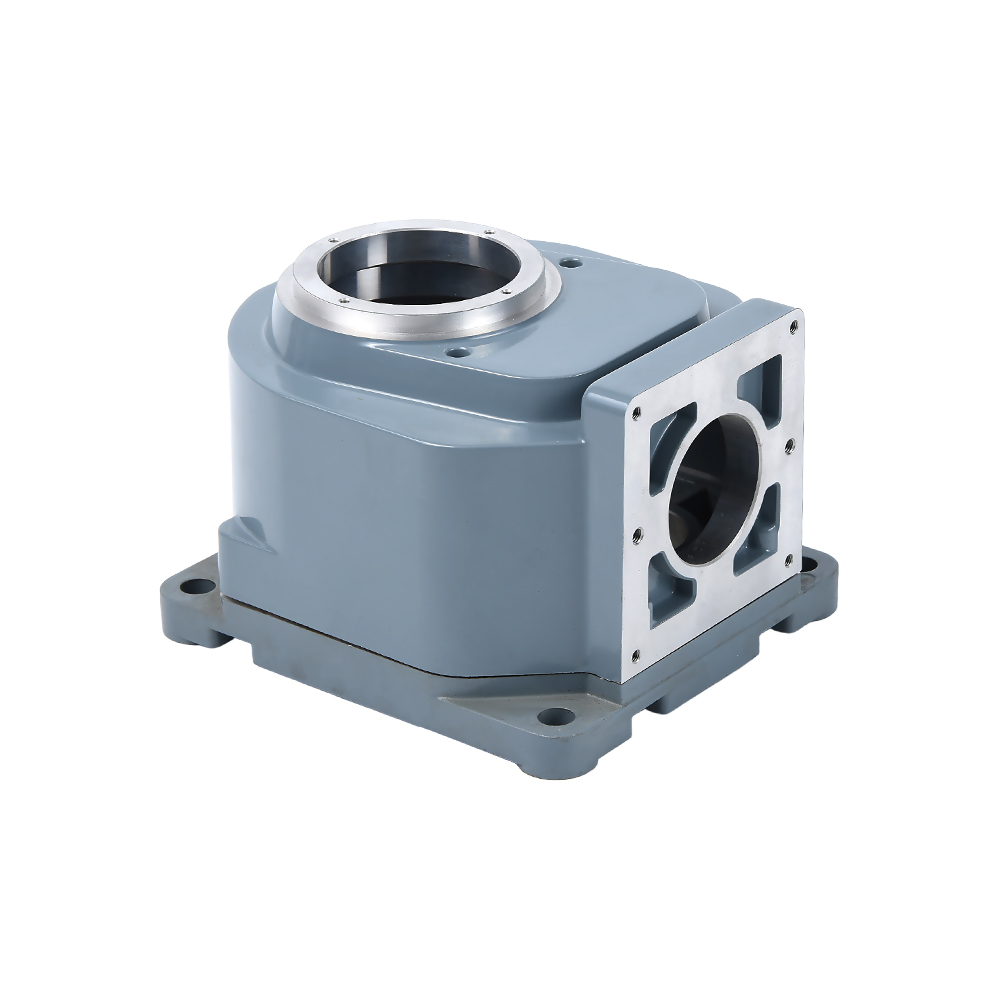
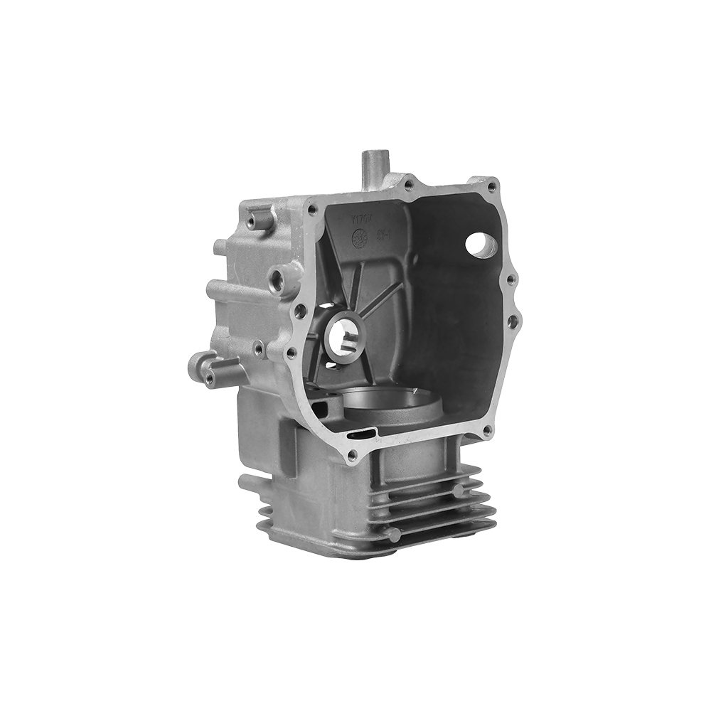
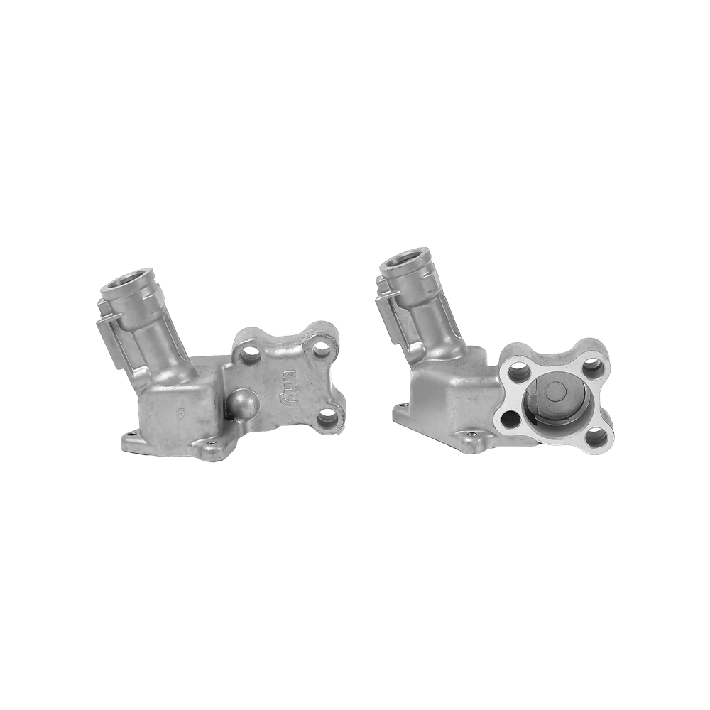
A custom aluminum casting is a metal part produced by pouring molten aluminum alloy into a mold shaped to the exact geometry a customer needs, rather than machining that shape from solid stock. For most functional parts with moderate to complex geometry, produced in volumes above a few hundred units, aluminum casting is cheaper per part than CNC machining and lighter than steel or iron casting for the same structural role. The right process choice almost always comes down to three variables: wall thickness, order volume, and dimensional tolerance. Thin, high-volume, tight-tolerance parts point toward die casting. Thick-walled, low-volume, or very large parts point toward sand casting. Complex internal geometry with no draft angle allowance points toward investment casting.
The rest of this guide walks through how each aluminum casting process actually performs against those three variables, which alloys make sense for which mechanical or thermal requirements, how a mold and gating system is actually engineered, how casting defects form and get prevented, how pricing is built up from tooling and material and labor, how casting compares against forging and machining as alternative processes, what a realistic prototype-to-production timeline looks like, and what a buyer should check before committing to a supplier such as Ningbo Beilun Youyuan Machinery Manufacturing Co., Ltd, which produces custom aluminum casting components across automotive, industrial equipment, and machinery housing applications.
Aluminum Casting Processes Compared: Sand, Die, Investment, and Gravity
Four processes cover roughly 95 percent of commercial aluminum casting work. Each trades tooling cost against unit cost differently, so the "best" process is really a function of order quantity and part complexity rather than a universal ranking.
High Pressure Die Casting
Molten aluminum is injected into a hardened steel mold under 1,500 to 25,000 psi of pressure and solidifies in seconds. This process suits thin walls (down to roughly 0.8 mm), tight tolerances, and production runs in the tens of thousands or more, because the steel tooling itself costs from several thousand to well over one hundred thousand dollars depending on part size and complexity. Die castings typically trap small amounts of gas porosity in the core, which limits heat treatment and welding but rarely affects parts that are not pressure-tested to high standards. Cycle times on a mid-size die casting machine typically run from 30 seconds to two minutes per shot, which is what makes die casting the only process capable of economically supplying automotive-scale volumes.
Sand Casting
Aluminum is poured into a mold made from sand bonded with resin or clay, then the mold is broken away after solidification. Tooling is a wood, plastic, or aluminum pattern that costs a fraction of die casting tooling, which makes sand casting the practical choice for prototypes, low-volume runs under roughly 500 units, and parts too large for a die casting machine. Wall thickness minimums run thicker, typically 4 to 6 mm, and surface finish is rougher than die casting, but the process handles parts from a few hundred grams up to several tonnes. Green sand, no-bake resin sand, and shell molding are the three common variants, and the choice between them mainly affects surface finish and dimensional repeatability rather than the fundamental economics of the process.
Investment (Lost-Wax) Casting
A wax pattern is coated in ceramic slurry to build a shell mold, then the wax is melted out before pouring. This process achieves the best dimensional accuracy and surface finish of the three, and it can produce geometry with no draft angle at all, which matters for parts with internal passages or intricate detail. It is slower and more expensive per part than either die or sand casting, so it tends to appear on aerospace brackets, valve bodies, and precision instrument housings rather than high-volume commodity parts. Because each wax pattern is typically injected from its own low-cost aluminum tool, small design revisions between prototype rounds are far less disruptive than a die casting tool change would be.
Gravity (Permanent Mold) Casting
Molten metal fills a reusable steel or iron mold under gravity alone, without the pressure used in die casting. The slower fill rate produces fewer trapped gas defects than die casting, so gravity-cast parts respond better to heat treatment and pressure testing. Tooling cost sits between sand casting and die casting, making this process a common middle ground for mid-volume parts, such as automotive suspension components or pump housings, that need better mechanical properties than a standard die casting can deliver. Low-pressure permanent mold casting, a close variant that fills the mold from below using modest air pressure, further reduces turbulence and is frequently specified for automotive road wheels precisely because it minimizes porosity in a part that must survive fatigue loading.
| Process | Tooling Cost | Min. Wall Thickness | Typical Tolerance | Best Order Volume |
|---|---|---|---|---|
| High Pressure Die Casting | High | 0.8–1.5 mm | ±0.1–0.3 mm | 10,000+ |
| Sand Casting | Low | 4–6 mm | ±0.5–1.5 mm | 1–500 |
| Investment Casting | Medium–High | 1.5–2.5 mm | ±0.1–0.4 mm | 100–5,000 |
| Gravity / Permanent Mold | Medium | 2.5–4 mm | ±0.3–0.8 mm | 500–10,000 |
Choosing the Right Aluminum Alloy for Custom Castings
Casting alloys are not interchangeable with wrought alloys such as 6061 or 7075, because casting compositions carry higher silicon content to improve fluidity and reduce shrinkage cracking during solidification. Picking the wrong casting alloy is one of the most common and most expensive mistakes in custom aluminum casting procurement, since a mid-production alloy change usually means new tooling trials.
A380 and ADC12: The Die Casting Workhorses
A380 (the North American designation) and ADC12 (its Japanese/Chinese equivalent) are the default alloys for die-cast parts that need good strength, decent corrosion resistance, and excellent castability at a low cost. They are not weldable in the conventional sense and cannot be heat-treated to significantly raise strength, but for housings, brackets, and covers that see moderate load, they cover the large majority of commercial die casting work. Typical as-cast tensile strength sits around 320 MPa with elongation near 3 percent, which is adequate for most non-structural enclosures but not for parts subject to repeated flex fatigue.
A356 and A357: Structural and Heat-Treatable Grades
A356 contains lower iron and is formulated for sand casting, gravity casting, and low-pressure die casting rather than high pressure die casting, because it needs the slower, lower-turbulence fill of those processes to avoid porosity. Its real advantage is heat treatability: after a T6 solution and aging treatment, A356 reaches tensile strength in the range of 275 to 310 MPa, which makes it the standard choice for structural automotive parts, wheels, and aerospace brackets that die-cast A380 cannot match. A357, a variant with added beryllium and slightly higher magnesium, pushes strength further still and appears in aerospace and defense castings where every extra percentage point of strength-to-weight matters.
LM6 / A413: Maximum Corrosion Resistance
With silicon content near the eutectic point (around 12 percent), this alloy family offers the best fluidity of any common casting alloy along with strong resistance to seawater and general atmospheric corrosion, at some cost to machinability. It shows up frequently in marine hardware, pump bodies, and outdoor enclosure castings.
A390: The High-Silicon, High-Wear Grade
At roughly 17 percent silicon, A390 is a hypereutectic alloy that produces hard silicon particles distributed through the microstructure, giving it excellent wear resistance without a separate hard coating. It is more difficult to machine than the alloys above because those same silicon particles are abrasive to cutting tools, but for cylinder bores, compressor components, and other surfaces that see sliding wear, it often eliminates the need for a liner or coating altogether.
| Alloy | Primary Process | Heat Treatable | Best For |
|---|---|---|---|
| A380 / ADC12 | Die Casting | No | Low-cost housings, brackets, covers |
| A356 / A357 | Sand / Gravity / Low-Pressure Die | Yes (T6) | Structural and load-bearing parts |
| LM6 / A413 | Sand / Die Casting | No | Marine and corrosion-exposed parts |
| A390 | Die Casting | Yes | High-wear surfaces, engine components |
Design Rules That Reduce Casting Defects and Cost
Most casting defects trace back to a small set of design choices made before the part ever reaches the foundry floor. Applying these rules early in a design review typically cuts scrap rate and eliminates a full round of tooling rework.
- Keep wall thickness uniform. Sudden transitions from thick to thin sections cause uneven cooling, which produces shrinkage porosity and warping at the transition point. A gradual taper over at least three times the thickness difference solves most of this.
- Add draft angle to every vertical face. A minimum of 1 to 2 degrees on die-cast parts, and 3 degrees on sand-cast parts, allows the pattern or die to release without dragging or tearing the surface.
- Use generous fillets at internal corners, at least 0.5 times the wall thickness, since sharp internal corners concentrate stress and act as crack initiation points under load.
- Design ribs at 50 to 70 percent of the adjoining wall thickness rather than matching it, which avoids creating a thick section at the rib-to-wall junction that cools slower than the surrounding material.
- Locate parting lines on non-critical surfaces where possible, since flash and a visible seam line always form along the parting line and typically need secondary trimming.
- Avoid deep, narrow pockets that trap gas during mold fill; where a pocket is unavoidable, add a vent path or work with the foundry to place an ejector-adjacent vent in the tooling.
- Place bosses and mounting features away from thin walls where possible, since a boss protruding from a thin section creates a hot spot that cools last and shrinks disproportionately.
- Where a threaded hole must be cast rather than tapped after machining, plan for a thicker local boss around it, since threads cut directly into thin as-cast material strip out under normal fastener torque.
Mold Design and Gating System Fundamentals
The tool itself does as much to determine casting quality as the alloy or the machine settings, and buyers who understand the basic vocabulary of gating design get much more useful conversations with their foundry engineer.
Gates and Runners
The gate is the narrow channel where molten metal enters the part cavity, and the runner is the larger channel that feeds the gate from the sprue or shot sleeve. Gate size and placement control fill velocity and turbulence: a gate that is too small accelerates the metal to a velocity that atomizes it and traps air, while a gate placed at a thin section can freeze before the rest of the part fills, producing an incomplete casting known as a misrun.
Risers and Feeding
In sand, investment, and gravity casting, risers are reservoirs of molten metal attached to thick sections that solidify last. As the casting shrinks during cooling, the riser feeds additional liquid metal into that section to compensate, preventing the internal void that would otherwise form. Riser placement follows the same logic as wall thickness design: every thick section needs its own feed path back to a riser, or it becomes an isolated hot spot that shrinks internally with no way to compensate.
Venting
As metal fills the cavity, the air and mold gases already inside the cavity have to go somewhere. Vents are thin channels machined into the parting line or core that let gas escape while being too narrow for the higher-viscosity molten metal to flow through significantly. Under-vented tooling is one of the most common root causes of gas porosity that only appears after tooling has already been cut, which is why experienced foundries run a mold flow simulation before committing to steel.
Mold Flow Simulation
Software that models fill pattern, solidification sequence, and predicted porosity location lets an engineer catch misruns, air traps, and hot spots on screen before a single gram of aluminum is poured into real tooling. For any part with thin walls, complex ribbing, or a history of defects in a similar design, requesting a fill simulation report during the quoting stage is one of the highest-value questions a buyer can ask, because it turns a guess into a documented prediction that can be checked against the first sample.
How Casting Defects Form and How They Are Prevented
Understanding what each defect actually looks like, and what causes it, helps a buyer read an inspection report intelligently rather than simply accepting or rejecting parts on a pass/fail basis.
| Defect | What It Looks Like | Typical Cause | Prevention |
|---|---|---|---|
| Gas Porosity | Small round voids, often clustered | Trapped air or mold gas during fast fill | Vacuum-assist die casting, better venting |
| Shrinkage Porosity | Irregular voids at thick sections | Inadequate feeding as metal cools | Riser placement, uniform wall thickness |
| Cold Shut | Visible line where two flow fronts met without fusing | Metal cooling before flow fronts merge | Higher pour temperature, better gate placement |
| Misrun | Incomplete filling, thin sections not formed | Metal freezing before cavity fills | Larger gates, thicker minimum walls |
| Hot Tearing | Jagged crack, often at a thick-thin junction | Stress during solidification shrinkage | Generous fillets, uniform cooling design |
| Inclusions | Hard particles visible on machined surface | Oxide film or refractory debris in melt | Filtration, degassing, clean melt handling |
A well-run foundry does not eliminate every defect risk through inspection alone; it designs the risk out through gating, alloy selection, and melt handling, then uses inspection to confirm the process is holding rather than to catch problems after the fact. This is why the process controls a supplier applies before the pour matter at least as much as the test equipment on the inspection floor.
Dimensional Tolerances and Quality Control for Aluminum Castings
Standard as-cast tolerances for die casting fall in the range of ±0.1 to ±0.3 mm for the first 25 mm of a dimension, with an additional allowance of roughly ±0.02 mm per additional 25 mm. Sand casting tolerances are considerably looser, generally ±0.5 mm or more, because the mold itself is consumed and rebuilt for every pour, introducing more variation between parts. Where a design calls for tighter tolerances than the casting process can hold, the practical solution is to cast slightly oversized in the critical feature and finish that feature with CNC machining after casting.
Quality verification on custom aluminum castings typically combines several inspection methods rather than relying on one:
- Dimensional inspection with a coordinate measuring machine (CMM) against the part's engineering drawing.
- X-ray or CT scanning to detect internal shrinkage porosity or gas voids that are invisible from the outside.
- Dye penetrant inspection for surface-breaking cracks, particularly on parts that will be pressure-tested.
- Spectrometer analysis of alloy composition to confirm the melt matches the specified alloy grade, batch to batch.
- Pressure or leak testing for parts such as pump housings or manifolds that must hold a fluid or gas seal.
- First-article inspection reports that document every dimension on the drawing against the actual measured part before a production run is approved.
For programs with recurring production, a control plan that specifies inspection frequency, sample size, and which dimensions are checked every batch versus periodically keeps quality consistent without inspecting every single part at full CMM detail, which would be too slow and costly to sustain at volume.
Surface Finishing and Post-Casting Machining Options
An as-cast aluminum surface is rarely the final surface a customer receives. The finishing step chosen affects corrosion resistance, appearance, and how the part interfaces with mating components.
Mechanical Finishing
Shot blasting and vibratory tumbling remove residual sand or die-release residue and even out surface texture across the part, and are typically the first finishing step regardless of what comes after. Deburring, whether manual, tumbled, or CNC-based, removes the flash line left along the parting line before any coating is applied.
Chemical and Electrochemical Finishing
Anodizing builds a controlled oxide layer that significantly improves corrosion and wear resistance and can be dyed for color; it is widely used on parts exposed to weather or handling wear. Chromate conversion coating offers a thinner corrosion-resistant layer, often used as a paint base rather than a standalone finish. Powder coating applies a durable, chip-resistant colored finish and is common on enclosures and housings that need a consumer-facing appearance. Electroless nickel plating is sometimes specified where a part needs a hard, uniform, solderable surface, particularly on connector housings and electronics enclosures.
CNC Machining After Casting
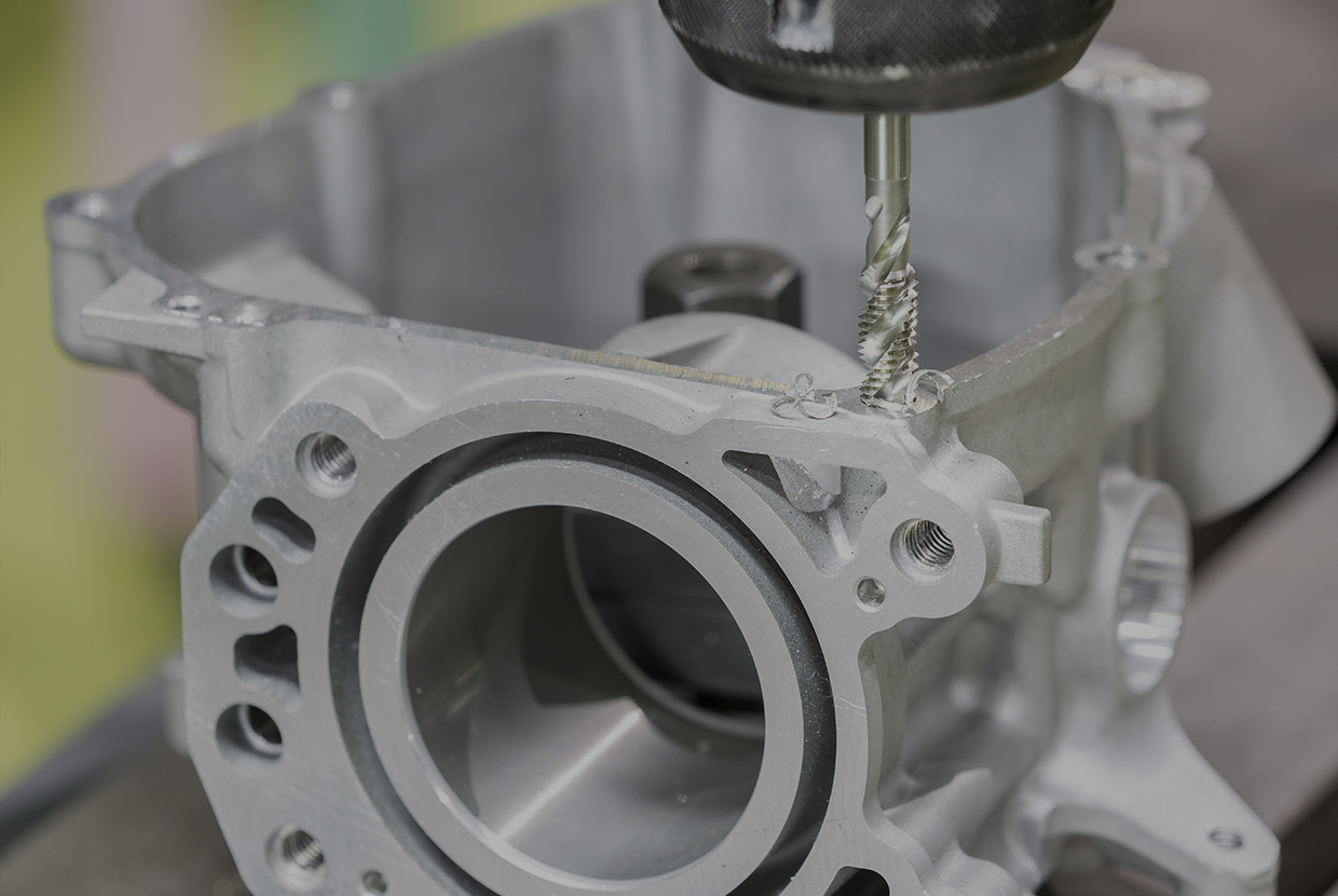
Mounting faces, bore diameters, threaded holes, and any feature with a tolerance tighter than the casting process can hold are machined after casting rather than cast to final size. Designing the casting with machining stock, typically 0.5 to 1.5 mm per side on critical faces, keeps the secondary machining pass light and predictable. Fixturing for this secondary machining step is usually built around a cast datum feature specifically added to the design for that purpose, which keeps repeat setups consistent across a production run.
Where Custom Aluminum Castings Are Used
Aluminum casting sits in the middle ground between plastic molding and steel fabrication: lighter than steel at comparable strength, more heat-resistant and rigid than most plastics, and more cost-effective than machined aluminum for medium to high production volumes. That combination puts custom aluminum castings across a wide span of industries.
| Industry | Typical Parts | Driving Requirement |
|---|---|---|
| Automotive | Transmission housings, brackets, pump bodies | Weight reduction, heat dissipation |
| Industrial Equipment | Gearbox covers, motor housings, valve bodies | Dimensional stability under load |
| Lighting and Electronics | LED heat sinks, enclosures, junction boxes | Thermal conductivity, EMI shielding |
| Marine Hardware | Fittings, pump housings, deck hardware | Corrosion resistance |
| HVAC and Fluid Handling | Pump impellers, manifolds, compressor housings | Pressure integrity, thermal performance |
Casting vs Forging vs CNC Machining vs Stamping
Aluminum casting is one of several ways to make a metal part, and it is not always the right one. Understanding where it fits against the alternatives prevents the common mistake of designing a part around the wrong process before quotes are even requested.
Casting vs Forging
Forging deforms solid metal under compressive force rather than pouring it as a liquid, which aligns the internal grain structure with the part's shape and produces higher fatigue strength and toughness for a given alloy. Forging tooling and process cost more than casting for equivalent volumes, and forging cannot economically produce the internal cavities, thin walls, or complex external geometry that casting handles easily. Forging tends to win for safety-critical, high-load parts such as steering knuckles or highly loaded structural brackets, while casting wins for geometry-complex parts where the load is moderate.
Casting vs CNC Machining
Machining from billet avoids tooling investment entirely and offers the tightest achievable tolerances, but it removes material as scrap and takes longer per part as geometry complexity rises. Below a few hundred units, or for a part with simple geometry, machining is often the lower-cost path. Above that volume, or for a part with significant internal complexity, casting followed by light finish machining on critical features usually wins on total cost.
Casting vs Stamping
Sheet metal stamping forms flat aluminum stock into shape using a die and press, and it is the far cheaper option for parts that are essentially two-dimensional with consistent wall thickness, such as brackets and covers with formed flanges. It cannot produce the three-dimensional internal geometry, variable wall thickness, or integrated bosses and ribs that casting can, so the choice between the two is usually clear once the part geometry is defined rather than a genuinely close call.
From Prototype to Production: A Realistic Project Timeline
Buyers new to custom aluminum casting are frequently surprised by how much of the total program timeline sits in tooling and validation rather than in the casting operation itself. A representative sequence for a new die-cast part looks like this:
- Design for manufacturability (DFM) review of the 3D model, typically 3 to 5 business days, identifying wall thickness, draft, and undercut issues before tooling starts.
- Mold flow simulation and gating design, run in parallel with tooling quotation, usually 1 to 2 weeks.
- Tooling fabrication, the longest single step, typically 3 to 6 weeks for a moderately complex die casting die.
- T1 sample trial and first-article inspection, comparing the initial cast samples against the drawing, roughly 1 week including any minor tool adjustment.
- Tool adjustment and T2 sample confirmation if the first trial reveals dimensional or cosmetic issues, adding 1 to 2 weeks when needed.
- Production ramp-up and ongoing batch delivery, with steady-state lead time per order typically 1 to 3 weeks once tooling is validated.
Sand casting and investment casting programs generally move faster through the tooling phase, since pattern or wax-tool fabrication is quicker and cheaper than steel die machining, but they carry the same fundamental sequence of design review, sample validation, and production ramp.
How Custom Aluminum Casting Is Priced
A casting quote is built from several distinct cost components, and understanding each one helps a buyer evaluate whether a quote is reasonable rather than simply comparing bottom-line numbers between suppliers.
- Tooling cost, a one-time charge amortized across the program, driven by part size, cavity count, and complexity of slides or lifters needed to release undercuts.
- Raw material cost, based on part weight plus the runner and gate system that solidifies alongside the part and is later trimmed off and recycled.
- Machine cycle time and labor, which scales with part size, wall thickness, and cooling time required before the part can be safely ejected.
- Secondary operations, covering trimming, deburring, machining, and any coating or plating specified on the drawing.
- Inspection and packaging, which scale with the inspection plan agreed for the program and any special handling the part requires for shipping.
Order volume affects unit price mainly through tooling amortization: a die that costs twenty thousand dollars adds two dollars per part across ten thousand units but only twenty cents per part across one hundred thousand units, which is why casting quotes typically show a step change in unit price at higher volume brackets even though the per-part manufacturing cost barely changes.
Recycled Content and the Environmental Profile of Aluminum Casting
Aluminum is one of the most recyclable engineering metals in commercial use, and remelting recycled aluminum consumes a small fraction of the energy required to produce new aluminum from bauxite ore. Casting alloys in particular are well suited to recycled content because the higher silicon composition tolerates the minor impurity variation that comes with scrap-based feedstock better than some wrought alloys do. In practice, this means gating and runner systems trimmed off during casting, along with reject parts, are routinely remelted and returned to the production stream rather than discarded, and many foundries run melts with a substantial proportion of recycled material without any measurable difference in the finished part's mechanical properties.
Packaging, Traceability, and Shipping Considerations
Custom aluminum castings that will be exported internationally need packaging specified as part of the program, not treated as an afterthought once parts are ready to ship. Machined surfaces are typically protected with a rust-preventative coating or wrapping film even though aluminum does not rust the way steel does, because handling marks and oxidation staining on a cosmetic surface are still a quality concern for the end customer. Parts are commonly packed in individual trays or dividers to prevent surface-to-surface contact damage during transit, and batch traceability, tying each shipped lot back to its melt certificate and inspection record, is standard practice for any program supplying regulated industries such as automotive or marine equipment.
Working With a Custom Aluminum Casting Manufacturer
The technical decisions above only pay off if the manufacturing partner can execute them consistently, batch after batch. Ningbo Beilun Youyuan Machinery Manufacturing Co., Ltd works with customers from initial part review through tooling, casting, machining, and finishing, covering the alloy selection, process selection, and inspection steps described throughout this guide under one roof rather than splitting them across separate vendors. For a buyer evaluating any aluminum casting supplier, a few practical checkpoints matter more than a general capability list:
- Ask for the specific alloy certificate and spectrometer report for the production batch, not just a general material datasheet.
- Confirm which inspection methods are standard versus optional add-ons, particularly X-ray or CT scanning for pressure-critical parts.
- Request a first-article sample and full dimensional report before authorizing production volume, even on repeat programs.
- Clarify machining capability and tolerance capability in-house versus outsourced, since outsourced secondary operations add lead time and another handoff where errors can enter.
- Ask whether mold flow simulation is run before tooling is cut, since this single step catches a disproportionate share of avoidable defects before they become physical scrap.
A supplier that can walk through wall thickness, alloy trade-offs, and tolerance stack-up during the quoting stage, rather than after the first sample fails, is generally the one worth building a long-term aluminum casting program with.
Frequently Asked Questions About Custom Aluminum Castings
How much does custom aluminum casting tooling cost?
Sand casting patterns typically run from a few hundred to a few thousand dollars. Gravity and investment casting tooling generally falls between two thousand and fifteen thousand dollars depending on part size. Die casting dies are the most expensive, commonly ranging from eight thousand dollars for a small simple part to well over one hundred thousand dollars for a large, multi-slide, high-cavity tool.
What is the minimum order quantity for a custom aluminum casting?
Sand casting and investment casting can be economical for order quantities as low as a few dozen to a few hundred parts, since tooling cost is comparatively low. Die casting generally only becomes cost-effective above a few thousand parts once the higher tooling investment is factored in, though this varies by part size and complexity.
Can aluminum castings be welded?
Wrought and low-silicon casting alloys such as A356 weld reasonably well with proper preheat and filler selection. High-silicon die casting alloys such as A380 and ADC12 are difficult to weld cleanly because trapped gas porosity from the casting process tends to boil and create weld defects; mechanical fastening or adhesive bonding is usually preferred for these alloys instead.
How long does it take to get a custom aluminum casting produced?
New tooling typically takes two to six weeks to design and build, depending on part complexity and process. Once tooling is validated, production lead time for a standard order usually runs one to three weeks, though this depends on order volume, alloy availability, and whether secondary machining or finishing is required.
What causes porosity in aluminum castings and can it be prevented?
Porosity comes from two sources: trapped gas during rapid mold fill, most common in die casting, and shrinkage as the metal solidifies and contracts, most common at thick sections without adequate feeding. Vacuum-assisted die casting reduces gas porosity, while proper riser placement and uniform wall thickness reduce shrinkage porosity. Neither defect can be fully eliminated in every process, which is why pressure-critical parts are typically specified in gravity or low-pressure casting rather than high-pressure die casting.
Is aluminum casting more cost-effective than CNC machining from billet?
For simple geometry in low volumes, machining from billet is often cheaper because it avoids tooling cost entirely. Once a part's geometry is complex enough to require extensive material removal, or once volume rises into the hundreds or thousands of units, casting becomes cheaper per part because tooling cost is spread across the run and less material is wasted as scrap.
Can a die-cast aluminum part be heat treated?
Standard high-pressure die casting traps enough internal gas porosity that solution heat treatment often causes blistering, as trapped gas expands under the treatment temperature. This is why die-cast alloys such as A380 are typically used as-cast or with a low-temperature stress relief only. Where heat treatment is required for higher strength, the part is usually produced by gravity casting, low-pressure casting, or vacuum-assisted die casting instead, all of which trap far less internal gas.
What is the difference between as-cast surface finish and machined surface finish?
An as-cast surface reflects the texture of the mold or die cavity itself, typically in the range of 3 to 6 micrometers Ra for die casting and considerably rougher for sand casting. A machined surface can be finished to well under 1 micrometer Ra where needed, which is why sealing faces, bearing bores, and any surface requiring a precise fit are specified as machined rather than left as-cast.
How do I know which wall thickness my part needs?
Wall thickness is set by the load the part must carry, the casting process chosen, and the alloy's mechanical properties, not by a single fixed rule. As a starting point, most die-cast structural sections fall between 2 and 4 mm, while sand-cast structural sections typically run 5 to 10 mm; a foundry's engineering team can refine this figure once the loading conditions and safety factor for the specific part are known.
What certifications or documentation should a casting supplier provide?
At minimum, a supplier should be able to provide a material certificate confirming alloy composition for the production batch and a dimensional inspection report against the customer's drawing. For automotive, marine, or other regulated programs, additional documentation such as process control plans, batch traceability records, and specific test reports for pressure or fatigue requirements are typically requested and agreed at the start of the program rather than after parts have shipped.