English
 русский
 Español
Content
- 1 How Long Does Die Casting Take? The Direct Answer
- 2 The Die Casting Process: Stage-by-Stage Time Breakdown
- 3 Typical Cycle Times by Alloy and Part Type
- 4 Factors That Control How Long Die Casting Takes
- 5 Die Casting Lead Times: From Design to First Production Part
- 6 Hot Chamber vs Cold Chamber Die Casting: Time Comparison
- 7 How Die Casting Compares to Other Manufacturing Processes in Speed
- 8 Strategies to Reduce Die Casting Cycle Time
- 9 Post-Casting Operations and Their Time Requirements
- 10 Common Misconceptions About Die Casting Time
How Long Does Die Casting Take? The Direct Answer
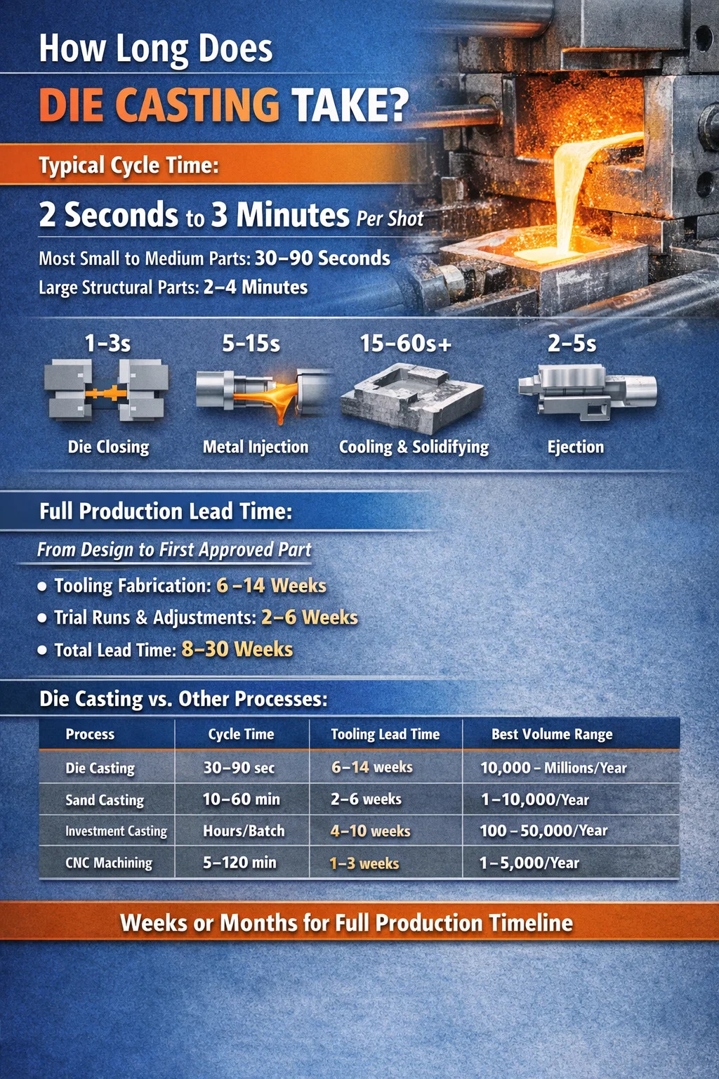
A single die casting cycle typically takes anywhere from 2 seconds to 3 minutes, depending on part size, alloy type, wall thickness, and machine configuration. For most small-to-medium aluminum or zinc components — the kind used in automotive brackets, housings, and consumer electronics — a realistic cycle time falls between 30 and 90 seconds. Large magnesium or aluminum structural parts for electric vehicles may push that window to 2–4 minutes per shot.
That cycle time figure only tells part of the story. Before the first good part rolls off the line, a die casting operation involves tooling fabrication (which can take 6–14 weeks), machine setup, die preheating, trial shots, and dimensional validation. From raw design to approved production part, the full timeline is measured in weeks or months, not seconds.
Understanding both the per-shot cycle and the total production timeline helps buyers, engineers, and operations teams set realistic expectations and avoid costly scheduling errors.
The Die Casting Process: Stage-by-Stage Time Breakdown
Every die casting cycle consists of several sequential stages. Each one consumes time, and delays in any stage cascade into the overall cycle. Here is what actually happens inside each shot:
Die Closing and Clamping
The two halves of the die — the fixed die half and the ejector die half — are brought together and locked under high clamping force. For a 400-ton cold chamber machine, this step takes roughly 1–3 seconds. Larger machines with higher tonnage ratings move more mass and may require 3–5 seconds just to close and confirm lock. Insufficient clamping force leads to flash defects, so this step cannot be rushed arbitrarily.
Metal Injection
Molten metal is forced into the die cavity under pressure. In hot chamber die casting — used mainly for zinc, lead, and tin alloys — the injection mechanism is submerged in the melt, so fill time is extremely fast: 0.01 to 0.5 seconds. In cold chamber die casting — used for aluminum, copper, and magnesium — metal must first be ladled into a separate shot sleeve, adding a few seconds before injection begins. The actual cavity fill in cold chamber processes still happens in 0.01 to 0.1 seconds, but the total injection phase including ladling is closer to 5–15 seconds.
Solidification and Cooling
This is the single longest phase in most die casting cycles. After injection, the metal must cool enough to develop sufficient structural rigidity for ejection without distortion. Cooling time depends on part geometry, wall thickness, alloy properties, and how well the die's water cooling channels are designed and maintained.
Thin-walled zinc parts (1.5–2.5 mm walls) may solidify in 3–8 seconds. Aluminum parts with 3–5 mm walls typically need 15–40 seconds. Thick structural aluminum castings with 6–10 mm sections can require 60–120 seconds or more. Reducing cooling time without inducing porosity or warpage is one of the primary engineering challenges in high-volume die casting.
Die Opening and Part Ejection
Once the part is solid enough, the die opens and ejector pins push the casting out of the cavity. This mechanical sequence typically takes 2–5 seconds. Parts drop onto a conveyor or into a quench tank. The ejection force must be calibrated carefully — too little and the part sticks; too much and thin features break or deform.
Die Lubrication and Reset
After ejection, robots or spray systems apply die release lubricant (typically water-based) to the cavity surfaces. This prevents sticking and helps manage die temperature. Spray time varies from 2 to 10 seconds depending on die complexity and the number of spray nozzles. Blow-off cycles to clear excess lubricant add another 1–3 seconds. The die then closes and the next cycle begins.
Typical Cycle Times by Alloy and Part Type
Different alloys have different thermal properties, injection pressures, and solidification behaviors. The table below shows representative cycle times for common die casting materials across part size categories:
| Alloy | Part Size | Typical Cycle Time | Process Type |
|---|---|---|---|
| Zinc (Zamak) | Small (<100g) | 2–10 seconds | Hot chamber |
| Zinc (Zamak) | Medium (100–500g) | 10–30 seconds | Hot chamber |
| Aluminum (ADC12 / A380) | Small (<300g) | 20–45 seconds | Cold chamber |
| Aluminum (ADC12 / A380) | Medium (300g–2kg) | 45–90 seconds | Cold chamber |
| Aluminum (structural) | Large (>2kg) | 90–180 seconds | Cold chamber |
| Magnesium (AZ91D) | Small to medium | 15–50 seconds | Hot or cold chamber |
| Copper / Brass | Small to medium | 30–90 seconds | Cold chamber |
Zinc consistently produces the shortest cycle times because of its lower melting point (approximately 380–420°C), faster solidification, and compatibility with hot chamber machines that eliminate the ladling step. Aluminum requires significantly more cooling time due to its higher thermal mass and pouring temperature (620–680°C). Copper alloys, with pouring temperatures above 900°C, demand robust die materials and extended cooling, making them among the slowest in die casting.
Factors That Control How Long Die Casting Takes
Cycle time is not an arbitrary number assigned by the machine manufacturer. It results from specific physical and process variables that engineers can measure, model, and — to a significant extent — control. The most impactful factors are:
Wall Thickness and Part Geometry
Cooling time scales roughly with the square of wall thickness. Double the wall thickness and you roughly quadruple the required cooling time, all else equal. A part with a 3 mm nominal wall that cools in 20 seconds will need approximately 80 seconds if redesigned to 6 mm. This is why design for manufacturability (DFM) reviews consistently push for uniform, thin walls — not just to save material, but to keep cycle times and per-piece costs manageable.
Geometry also affects fill time. Complex cavities with narrow runners, thin ribs, and multiple cores require slower injection speeds or risk turbulence-induced porosity. Parts with deep pockets or undercuts need side actions (sliding cores) that add mechanical steps to opening and closing sequences.
Die Temperature Management
Die temperature has a direct and powerful effect on cycle time. Dies that run too cold cause premature solidification, misruns, and cold shuts. Dies that run too hot extend cooling time and risk soldering (metal sticking to the die). The optimal die temperature window for aluminum die casting is typically 150–250°C at the cavity surface, maintained through a combination of internal water cooling channels and external spray cooling.
Die temperature controllers (DTCs) circulate heated water or oil through the die to stabilize temperature during startup and maintain it during sustained production. A well-designed cooling circuit can cut solidification time by 20–35% compared to an unoptimized die of the same geometry. Poorly placed cooling lines — too far from thick sections — leave hot spots that force operators to extend cooling time artificially to avoid warped or blistered parts.
Machine Tonnage and Speed
Higher tonnage machines move heavier platens and require more time for die open and close strokes, even with fast hydraulic or electric drives. A 160-ton machine might complete a clamp cycle in 1.5 seconds; a 2,000-ton machine doing structural automotive parts may take 5–8 seconds just for clamping. Electric die casting machines (servo-driven) generally achieve faster and more repeatable clamp and injection motions than older hydraulic-only machines, often trimming 2–5 seconds per cycle on medium-sized parts.
Number of Cavities
Multi-cavity dies produce more parts per shot without increasing cycle time proportionally. A single-cavity die for a small zinc connector might run at 15 seconds per cycle, yielding 4 shots per minute. A 16-cavity die for the same part on the same machine still runs at roughly 15–20 seconds per cycle, but now produces 16 parts per cycle rather than one — effectively reducing per-piece time from 15 seconds to under 1.5 seconds. The tradeoff is higher die cost (a 16-cavity zinc die can cost $80,000–$150,000 vs $15,000–$30,000 for single cavity) and more complex quality control.
Automation Level
Manual operations — where an operator ladles metal, removes parts by hand, and sprays the die with a handheld gun — introduce cycle time variability of 10–30%. Robotic extraction, automated spray systems, and integrated trimming presses remove this variability. In fully automated high-volume plants producing automotive parts, cycle-to-cycle variation is routinely held to under 1 second, enabling accurate throughput forecasting and consistent metallurgical quality.
Die Casting Lead Times: From Design to First Production Part
For buyers and project managers, the cycle time per shot is often less immediately relevant than the total lead time from purchase order to first approved shipment. This timeline breaks into several distinct phases:
Tooling Design and Fabrication
Die casting dies are complex, precision-machined tools made from H13 hot work tool steel or equivalent grades. A medium-complexity aluminum die casting tool — single cavity, moderate geometry, no side actions — typically takes 6–10 weeks to fabricate from approved design. Dies with multiple side actions, complex internal cooling, or tight dimensional tolerances may take 10–16 weeks. Tooling cost ranges from approximately $15,000 for a simple zinc die to over $300,000 for a large structural aluminum die with vacuum systems and multiple cores.
Suppliers in China and Southeast Asia often quote 4–6 weeks for tooling, but this frequently excludes design review cycles and may involve compressed timelines that increase trial shot count and delay part approval.
Trial Shots and Part Qualification
After the die is installed on the machine, the process begins with T1 (first trial) shots. These initial shots are used to establish basic process parameters — injection speed, fill pressure, die temperature, and cooling time. It is extremely rare for a die to produce conforming parts on the first day of trials. Most programs budget 2–4 rounds of trials over 2–6 weeks to tune the process, address dimensional deviations, and resolve surface defects.
Automotive-grade die castings require PPAP (Production Part Approval Process) or equivalent documentation, including dimensional reports, material certifications, and process capability studies (Cpk ≥ 1.67 on critical features). This documentation phase can add another 2–4 weeks after parts pass dimensional inspection.
Total Lead Time Summary
- Simple part, no side actions, non-automotive: 8–14 weeks from tooling order to first approved shipment
- Medium complexity automotive die casting: 14–22 weeks
- Large structural part with vacuum die casting and PPAP: 20–30 weeks
- Prototype die casting (soft tooling, aluminum or kirksite dies): 2–4 weeks, limited volume, lower accuracy
Hot Chamber vs Cold Chamber Die Casting: Time Comparison
The two main die casting process categories differ significantly in speed because of their fundamental mechanical architecture:
Hot Chamber Die Casting
In hot chamber machines, the injection cylinder (gooseneck) is permanently submerged in the molten metal bath. When the plunger retracts, metal fills the chamber automatically. When it advances, metal is forced through the gooseneck and into the die. Because there is no separate ladling step, cycle times are dramatically shorter — small zinc parts can cycle at 300–500 shots per hour on multi-cavity dies. This process is limited to low-melting-point alloys (zinc, lead, tin, some magnesium) because higher temperatures degrade the submerged components quickly.
Cold Chamber Die Casting
Cold chamber machines keep the injection mechanism separate from the melt furnace. An operator or automated ladle robot transfers a measured shot of metal into the shot sleeve before each cycle. This adds 5–15 seconds per cycle compared to hot chamber but allows processing of high-temperature alloys like aluminum, magnesium, and copper that would destroy a submerged gooseneck. The majority of die casting by weight — particularly automotive aluminum parts — uses cold chamber machines.
In practical terms, a zinc connector produced on a hot chamber machine might cost $0.08–$0.25 per piece in cycle time alone. The same part geometry redesigned in aluminum on a cold chamber machine could have cycle-time-related costs of $0.40–$1.20 per piece — a real cost driver in high-volume consumer electronics applications where hundreds of millions of units per year make every second count.
How Die Casting Compares to Other Manufacturing Processes in Speed
Die casting is one of the fastest methods for producing complex metal parts at scale, but its speed advantage is most pronounced at high volumes. A comparison with other common metal forming processes clarifies where die casting stands:
| Process | Cycle Time (medium part) | Tooling Lead Time | Best Volume Range |
|---|---|---|---|
| Die Casting | 30–90 seconds | 6–14 weeks | 10,000–millions/year |
| Sand Casting | 10–60 minutes | 2–6 weeks | 1–10,000/year |
| Investment Casting | Hours per batch | 4–10 weeks | 100–50,000/year |
| CNC Machining | 5–120 minutes | 1–3 weeks (fixtures) | 1–5,000/year |
| Permanent Mold Casting | 2–10 minutes | 4–8 weeks | 1,000–100,000/year |
Die casting's speed advantage over sand casting and investment casting is substantial — often 10x to 50x faster per part when running at full production. That speed advantage, combined with excellent dimensional repeatability (tolerances of ±0.1 mm on non-critical features are routinely held), explains why die casting dominates in automotive, consumer electronics, and appliance manufacturing at volumes above roughly 10,000 parts per year.
Strategies to Reduce Die Casting Cycle Time
In high-volume production, even a 5-second reduction in cycle time translates directly into measurable cost savings. A part running at 60 seconds per cycle on a machine with a $120/hour burden rate costs $2.00 per cycle. Reduce that to 50 seconds and the per-piece cost drops to $1.67 — a 16.5% reduction without changing material, labor, or overhead. At 1 million parts per year, that is a $330,000 annual saving from a single process improvement. The most effective cycle time reduction strategies are:
Optimize Cooling Circuit Design
Conformal cooling — where cooling channels follow the contour of the cavity rather than running in straight lines — can reduce cooling time by 20–40% compared to conventional drilled channels. Conformal channels are manufactured using additive manufacturing (3D printing of tool steel inserts) and position cooling water much closer to complex surfaces. The upfront tooling cost premium (typically $10,000–$40,000 extra per insert set) is recovered quickly in high-volume programs.
Use Intensification Pressure Properly
Applying high intensification pressure (2nd phase pressure) immediately after cavity fill forces metal into every detail and compensates for shrinkage during solidification. Proper intensification reduces microporosity, which in turn allows thinner walls — which cool faster. This is an indirect but effective route to shorter cycle times through improved part design confidence.
Minimize Ejection Temperature
Parts can be ejected at higher temperatures than many operators assume, provided the geometry is not prone to warpage and ejector pin placement is correct. Testing with thermal imaging and warpage measurement allows teams to identify the minimum safe cooling time experimentally. Many production programs run 10–20% longer cooling times than necessary simply because they were never re-optimized after initial setup.
Implement Real-Time Process Monitoring
Modern die casting machines equipped with sensors on cavity pressure, plunger velocity, and die temperature can automatically adjust process parameters shot-to-shot. This adaptive control prevents the over-conservative cooling times that operators set manually to avoid occasional defective shots. Consistent process conditions also reduce scrap rates, which effectively improves net throughput without changing the machine cycle at all.
Redesign for Uniform Wall Thickness
Thick bosses, ribs, or pads that deviate significantly from nominal wall thickness create hot spots that dictate the minimum cooling time for the whole part. Coring out thick sections, adding radius transitions, and replacing solid pads with ribbed structures can eliminate these bottlenecks. In one documented automotive bracket redesign, reducing the maximum wall from 8 mm to 5 mm (while maintaining strength through rib geometry) cut cooling time from 75 seconds to 42 seconds — a 44% reduction that moved the part to a significantly smaller, cheaper machine class.
Post-Casting Operations and Their Time Requirements
The die casting shot is just the beginning. Most die cast parts require additional operations before they are ready to ship or assemble. These post-casting steps add time — sometimes more than the casting cycle itself — and must be planned into overall production scheduling:
- Trimming / Deflashing: Removal of flash (thin metal fins at parting lines) and runner/gate systems. Manual deflashing: 30–120 seconds per part. Automated trim press: 3–10 seconds per part.
- Shot blasting: Surface cleaning and texture improvement. Batch cycle: 5–15 minutes for a load of parts.
- CNC machining: Drilling, tapping, and precision-milling of cast surfaces. Time varies widely: 30 seconds to 10 minutes depending on features and fixturing.
- Heat treatment (T5/T6 for aluminum): Solution treating and artificial aging can take 6–24 hours total and requires batch oven scheduling.
- Surface finishing (anodizing, powder coating, painting): 1–48 hours depending on process and finish class.
- Inspection and dimensional measurement: CMM inspection on first articles or sample plans: 10–60 minutes per part for comprehensive reports.
When post-casting operations are included, the total manufacturing time per part at a job shop might be measured in hours or days rather than seconds. Efficient production cells combine robotic extraction, inline trim presses, and integrated conveyors to minimize the time between operations and reduce work-in-process inventory.
Common Misconceptions About Die Casting Time
Several persistent misunderstandings about die casting timelines cause problems in sourcing, program planning, and cost estimation:
"Die casting is always fast"
Die casting is fast for high-volume, repeat production of identical parts. It is not fast for low volumes, because the tooling lead time dominates the timeline. For a 500-piece prototype order, the 10-week tooling lead time makes die casting slower than CNC machining or even investment casting in terms of time-to-first-part. This is why prototype die casting with temporary aluminum tools exists as a category — it accepts compromised tool life to get parts faster.
"Faster cycle time always means lower cost"
Reducing cycle time below the process-stable minimum increases scrap rate and die maintenance frequency. A 10-second reduction in cooling time that increases scrap from 2% to 8% saves machine time but increases metal and rework costs. The optimum cycle time minimizes total cost per good part — not just machine time. This requires scrap and rework costs to be factored alongside machine burden rate.
"My supplier's quoted lead time is the total lead time"
Suppliers typically quote tooling lead time and sometimes T1 sample lead time. They rarely include time for design review iterations, customer-side dimensional approval, PPAP documentation preparation, or logistics. Buyers who take the quoted tooling time as the total time-to-production regularly find themselves 4–8 weeks behind schedule. A realistic program plan adds at least 3–6 weeks to the supplier's quoted number for part approval and supply chain setup.